vintage-taylor-dunn-electric-golf-cart-wiring-diagram.pdf
1 / 83
100%
Download Full Diagram Via this App!!!!
Get Diagram Now! DOWNLOAD NOW
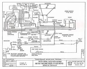 Title : Vintage Taylor Dunn Electric Golf Cart Wiring Diagram
Category : Wiring Diagram
Format : PDF
Title : Vintage Taylor Dunn Electric Golf Cart Wiring Diagram
Category : Wiring Diagram
Format : PDF