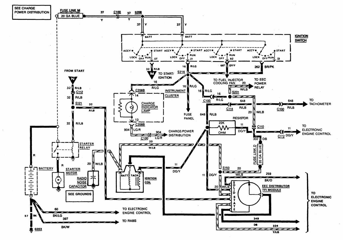
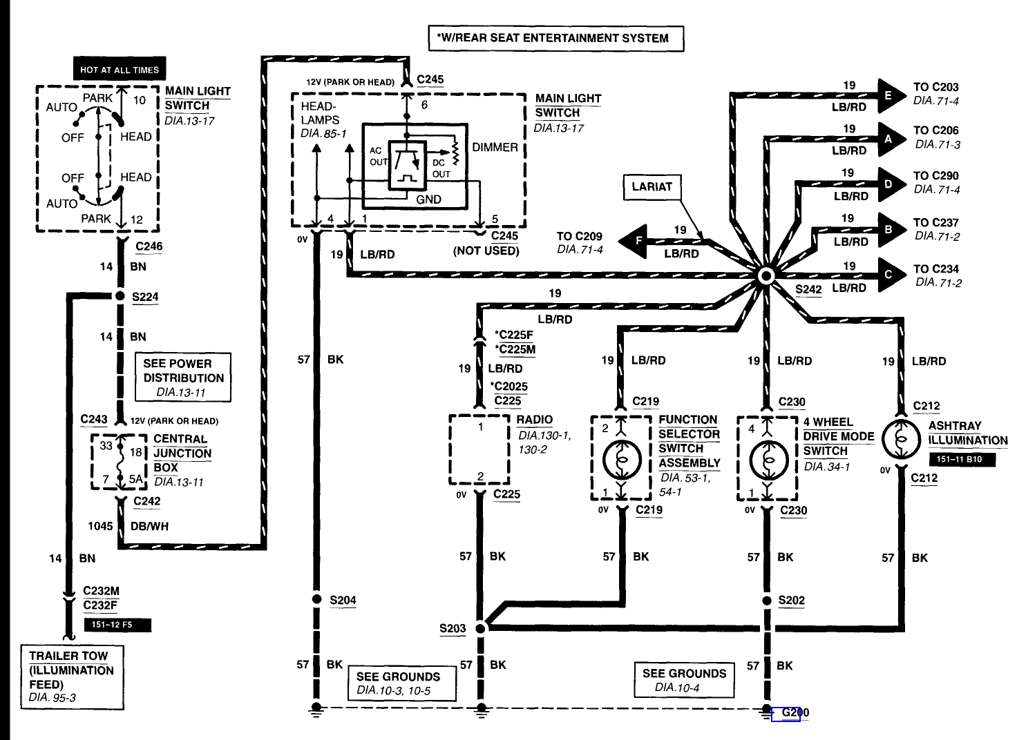
1000-images-about-auto-parts-for-your-ford-f150-f250-wiring-diagram.pdf
100%

1000 Images About Auto Parts For Your Ford F150 F250 Wiring Diagram


HTTP://WIRINGSCHEMA.COM
Revision 3.2 (12/2003)
© 2003 HTTP://WIRINGSCHEMA.COM. All Rights Reserved.

TABLE OF CONTENTS

Cover1
Table of Contents2
AIR CONDITIONING3
ANTI-LOCK BRAKES4
ANTI-THEFT5
BODY CONTROL MODULES6
COMPUTER DATA LINES7
COOLING FAN8
CRUISE CONTROL9
DEFOGGERS10
ELECTRONIC SUSPENSION11
ENGINE PERFORMANCE12
EXTERIOR LIGHTS13
GROUND DISTRIBUTION14
HEADLIGHTS15
HORN16
INSTRUMENT CLUSTER17
INTERIOR LIGHTS18
POWER DISTRIBUTION19
POWER DOOR LOCKS20
POWER MIRRORS21
POWER SEATS22
POWER WINDOWS23
RADIO24
SHIFT INTERLOCK25
STARTING/CHARGING26
SUPPLEMENTAL RESTRAINTS27
TRANSMISSION28
TRUNK, TAILGATE, FUEL DOOR29
WARNING SYSTEMS30
WIPER/WASHER31
Diagnostic Flowchart #332
Diagnostic Flowchart #433
Case Study #1 - Real-World Failure34
Case Study #2 - Real-World Failure35
Case Study #3 - Real-World Failure36
Case Study #4 - Real-World Failure37
Case Study #5 - Real-World Failure38
Case Study #6 - Real-World Failure39
Hands-On Lab #1 - Measurement Practice40
Hands-On Lab #2 - Measurement Practice41
Hands-On Lab #3 - Measurement Practice42
Hands-On Lab #4 - Measurement Practice43
Hands-On Lab #5 - Measurement Practice44
Hands-On Lab #6 - Measurement Practice45
Checklist & Form #1 - Quality Verification46
Checklist & Form #2 - Quality Verification47
Checklist & Form #3 - Quality Verification48
Checklist & Form #4 - Quality Verification49
AIR CONDITIONING Page 3

Every electrical system, whether in a car, manufacturing facility, or household device, relies on two fundamental pillars: **power distribution** and **grounding**. Without them, even the most advanced circuits would break down within seconds. This manual explores how electricity travels from its source to each load, how grounding stabilizes voltage levels, and how these two principles define the reliability and safety of every wiring system featured in 1000 Images About Auto Parts For Your Ford F150 F250 Wiring Diagram (Wiring Diagram, 2026, http://wiringschema.com, https://http://wiringschema.com/1000-images-about-auto-parts-for-your-ford-f150-f250-wiring-diagram/).

In any network of wires, current must always have a complete pathfrom the power source to the load and back through the ground or return line. Power distribution handles the delivery of energy, while grounding ensures that the system maintains a reference point close to zero volts. Together, they create the electrical loop that allows every motor, sensor, or controller to function as intended. Understanding this loop is essential for anyone who wants to repair or engineer electrical systems correctly.

Power distribution begins at the supply. In vehicles, its the battery or alternator; in buildings, its the main circuit panel; and in factories, it might be a three-phase transformer. The goal is to deliver consistent voltage to each branch circuit, ensuring no device receives too much or too little. The distribution path often includes switching relays, fuses, overload protectors, and connectors that isolate faults and protect sensitive electronics. A single bad connection or corroded fuse can drop voltage across the line, causing sensors to malfunction or actuators to operate erratically.

Grounding, on the other hand, serves as the stabilizing backbone of the entire system. Every piece of equipment must have a reliable ground connection to discharge stray current and prevent voltage buildup. Without proper grounding, static electricity, electromagnetic interference, and short circuits can cause erratic readings or even damage expensive modules. In an automotive context, the vehicle chassis often acts as a shared ground; in industrial panels, grounding bars connect all metallic enclosures to a dedicated earth rod. Proper grounding equals system stability thats a universal truth across Wiring Diagram and beyond.

When troubleshooting electrical problems, poor grounding is one of the most common culprits. A weak or corroded ground connection can mimic almost any fault intermittent lights, communication errors, or unexplained resets in control modules. Thats why professional technicians always start diagnostics by verifying voltage drop between ground points. A good rule of thumb is that no ground connection should drop more than **0.1 volts** under load. Anything higher indicates resistance that must be cleaned or repaired immediately.

Proper wiring design also ensures that current flow remains balanced. For example, heavy loads like motors should have thicker cables and separate grounds to prevent noise interference with low-voltage sensor circuits. Signal grounds, chassis grounds, and power grounds must be routed carefully to avoid feedback loops. In industrial automation, engineers often implement **star grounding**, where all grounds converge to a single point to minimize potential differences. This strategy prevents erratic readings in analog sensors and reduces communication errors on data buses.

Modern systems integrate **ground fault detection** to monitor leakage currents and automatically disconnect power if a fault is detected. This adds another layer of protection for both operators and equipment. Residual current devices (RCDs) and ground fault circuit interrupters (GFCIs) are common in residential and industrial environments, ensuring that stray current never becomes a safety hazard. These innovations reflect the evolution of safety standards recognized globally and practiced in facilities across Wiring Diagram.

Another key factor in power distribution is **voltage regulation**. Long wire runs or undersized cables can cause significant voltage drops, especially in high-current circuits. Using the correct wire gauge is crucial not only for performance but also for safety. Underrated cables heat up under load and can become a fire risk. Engineers calculate cable sizes based on current draw, material resistance, and permissible voltage loss. Regular maintenance, including checking torque on terminal screws and inspecting for oxidation, ensures that every joint maintains low resistance over time.

When it comes to documentation, detailed wiring diagrams serve as the map of the entire power and ground network. They show how each branch connects, where protective devices are located, and how current returns to the source. By following the diagram, technicians can isolate sections, perform continuity tests, and verify that each load receives proper voltage. The ability to read and understand these schematics turns complex troubleshooting into a logical, step-by-step process an approach fully explained throughout 1000 Images About Auto Parts For Your Ford F150 F250 Wiring Diagram.

In short, **power distribution delivers energy**, and **grounding keeps that energy under control**. Without either, no circuit could operate safely or predictably. Together, they define the health of every electrical system from the smallest sensor to the largest industrial controller. Understanding how to design, inspect, and maintain these two elements will make you far more effective in diagnosing faults and preventing downtime. Once you appreciate how current travels through every wire, and how grounding ensures balance and safety, wiring diagrams will no longer look like tangled lines but like living systems organized, logical, and perfectly engineered to make machines work, no matter the application or the year 2026.

Figure 1
ANTI-LOCK BRAKES Page 4

Safe electrical work is equal parts procedure and understanding. Before beginning work, identify the circuit’s voltage range, grounding points, and isolation methods. Use lockout-tagout procedures whenever possible to prevent accidental energizing. Never assume a system is de-energized — always verify with a calibrated meter.

Handling precision is critical once work begins. Avoid sharp kinks and never force a connector to seat by brute strength. Keep harnesses clear of hot housings, rotating parts, and bare metal corners. Use clear labeling to make future service faster and safer. Any missing boot or sleeve should be renewed to keep insulation integrity.

When you finish, examine everything under proper lighting conditions. Confirm that bolts are torqued, grounds are solid, and wiring is neatly routed. Clear debris and collect tools before sealing the system. Record what was done and do not approve the job until it meets safety criteria. A safe job is not just finished — it’s verified, recorded, and ready for operation.

Figure 2
ANTI-THEFT Page 5

Symbols in schematics are intentionally simplified. You’ll see resistors drawn as zigzags or rectangles, diodes as arrow+bar, and fuses as small loops labeled with their amp value. The goal is not physical appearance, it’s functional behavior of current and protection.

After that, short tags connect each symbol to its exact job. SW means switch, IGN means ignition feed, B+ means unswitched battery positive, TPS means throttle position sensor, CLK means timing/clock signal. Lines tagged CAN‑H and CAN‑L are the differential bus pair that carry communication for “1000 Images About Auto Parts For Your Ford F150 F250 Wiring Diagram”.

Before you clip a lead to “ground,” make sure that ground is the one you think it is. Chassis GND, shield ground, and sensor reference ground are intentionally separated, especially in export builds for Wiring Diagram. Mixing them can cause noise, drift, or total sensor failure in 2026; most notes from http://wiringschema.com and service refs at https://http://wiringschema.com/1000-images-about-auto-parts-for-your-ford-f150-f250-wiring-diagram/ call this out explicitly.

Figure 3
BODY CONTROL MODULES Page 6

Wire color coding and sizing form the essential framework for safe and efficient electrical installations.
Color shows a wire’s function at a glance, while gauge determines its current capacity and physical strength.
Typically, red = live, black/brown = ground, yellow = switch/ignition, and blue = control/signal.
Following these conventions ensures that technicians working on “1000 Images About Auto Parts For Your Ford F150 F250 Wiring Diagram” can instantly understand circuit layouts and avoid potentially dangerous mistakes.
A proper color and gauge system makes wiring easier to install, inspect, and maintain over the life of the equipment.

Gauge value, expressed in AWG or mm², defines current flow efficiency and voltage stability.
Thicker (low AWG) wires carry more current; thinner (high AWG) ones are designed for low-current circuits.
Proper wire sizing minimizes voltage fluctuation, limits heat, and extends component life.
Within Wiring Diagram, engineers use ISO 6722, SAE J1128, and IEC 60228 to guarantee consistent conductor ratings and durability.
Choosing the correct gauge ensures stability and protects high-load systems within “1000 Images About Auto Parts For Your Ford F150 F250 Wiring Diagram” from overheating.
Even a minor miscalculation in wire thickness can lead to unpredictable voltage fluctuations and potential safety hazards.

Accurate documentation ensures traceability, accountability, and professional execution for each wiring job.
Every color change, routing update, or size adjustment must be documented in the maintenance records.
When alternative materials or routing paths are used, these adjustments must be labeled and documented for future technicians.
All final diagrams, photos, and voltage test results should be uploaded to http://wiringschema.com to maintain a reliable record of work.
Listing year (2026) and linking to https://http://wiringschema.com/1000-images-about-auto-parts-for-your-ford-f150-f250-wiring-diagram/ builds an accessible record for long-term review.
With careful documentation, “1000 Images About Auto Parts For Your Ford F150 F250 Wiring Diagram” remains compliant, efficient, and safe for years of continued service.

Figure 4
COMPUTER DATA LINES Page 7

The foundation of stable electrical performance lies in proper power distribution.
It controls energy delivery from the supply to every circuit, component, and actuator, ensuring steady flow.
A well-engineered power network keeps voltage and current balanced throughout “1000 Images About Auto Parts For Your Ford F150 F250 Wiring Diagram”.
Such design avoids overloads, voltage dips, and premature component fatigue.
Essentially, power distribution converts unstable energy into a controlled, dependable system supply.

The first step in power system design is determining load requirements and proper branching.
Fuses, connectors, and cables should match the system’s load current with an adequate safety factor.
Engineers in Wiring Diagram typically follow standards like ISO 16750, IEC 61000, and SAE J1113 to guarantee safety and performance.
High-current wires must be kept apart from communication cables to minimize electromagnetic interference.
Fuse holders and ground points must be placed strategically for quick identification and service.
When well designed, “1000 Images About Auto Parts For Your Ford F150 F250 Wiring Diagram” stays stable and reliable under demanding operating conditions.

Once installed, the final phase involves testing and detailed documentation.
Technicians should measure voltage drop, check circuit resistance, and confirm that each fuse value matches design specifications.
Modifications during installation must be updated in drawings and digital records immediately.
All validation data and inspection images should be archived in http://wiringschema.com for future access.
Including the project year (2026) and related https://http://wiringschema.com/1000-images-about-auto-parts-for-your-ford-f150-f250-wiring-diagram/ maintains traceable quality documentation.
Proper documentation ensures “1000 Images About Auto Parts For Your Ford F150 F250 Wiring Diagram” stays reliable, easy to maintain, and compliant with standards.

Figure 5
COOLING FAN Page 8

Grounding serves as a safety channel that allows stray electricity to flow into the ground safely, protecting both people and systems.
It keeps electrical systems balanced by providing a stable voltage reference and avoiding current leakage into sensitive circuits.
A poorly grounded “1000 Images About Auto Parts For Your Ford F150 F250 Wiring Diagram” can lead to fluctuating current, signal distortion, and equipment breakdown.
Proper grounding boosts performance, minimizes repair frequency, and enhances safety margins.
In Wiring Diagram, grounding remains a critical standard for ensuring electrical systems operate efficiently and safely.

Designing a reliable grounding system begins with a complete assessment of soil conditions, electrical load, and fault current capacity.
Engineers should choose corrosion-resistant, conductive materials for stability and long service life.
Across Wiring Diagram, engineers follow IEC 60364 and IEEE 142 to ensure compliance with global grounding practices.
Grounding conductors should be interconnected in a loop to equalize potential throughout the network.
Bonding metal components to the grounding system ensures equal potential and safety continuity.
Through adherence to these standards, “1000 Images About Auto Parts For Your Ford F150 F250 Wiring Diagram” ensures consistent safety and optimal function.

Regular testing and preventive maintenance help sustain the efficiency of grounding systems.
Inspectors should test resistance, verify circuit continuity, and review all joint integrity.
Any corrosion or wear should be corrected immediately and verified with post-maintenance testing.
Grounding reports should be filed and archived for future verification and compliance.
Annual or post-modification testing ensures the grounding system remains effective.
Consistent upkeep and testing ensure “1000 Images About Auto Parts For Your Ford F150 F250 Wiring Diagram” remains safe, stable, and reliable for years.

Figure 6
CRUISE CONTROL Page 9

1000 Images About Auto Parts For Your Ford F150 F250 Wiring Diagram – Connector Index & Pinout Guide 2026

Connectors in automotive wiring systems differ by function, material, and environmental protection level. Each design serves specific electrical or data-transmission purposes. Ranging from sensor couplers to power-distribution plugs, all connectors maintain stable current transfer.

Inline connectors are commonly used to link two harness sections and are often sealed with rubber grommets for water resistance. Multi-pin connectors are utilized in ECUs, lighting assemblies, and control modules to organize multiple signal lines in one compact housing. Heavy-duty terminal connectors manage power lines; sensor plugs stay small to save space.

Each connector features a unique locking system, pin arrangement, and keying pattern to prevent mismatching. By recognizing key shapes and latch mechanisms, maintenance becomes quicker and more secure. A trained eye for connector design keeps systems reliable through years of operation.

Figure 7
DEFOGGERS Page 10

1000 Images About Auto Parts For Your Ford F150 F250 Wiring Diagram Full Manual – Sensor Inputs Reference 2026

Speed input circuits allow control modules to synchronize motion and performance precisely. {Common examples include wheel speed sensors, crankshaft position sensors, and transmission output sensors.|These sensors generate frequency-based signals corresponding to shaft or wheel movement.|Each ...

Hall-effect sensors produce voltage pulses when a magnetic target passes near the sensing element. {Optical sensors use light interruption or reflection to measure rotational motion accurately.|Each method converts physical movement into an electronic pulse signal.|The ECU interprets these pulses to calculate real-time spe...

Faulty speed sensors can trigger warning lights or cause unstable performance such as erratic shifting or traction loss. {Understanding how speed sensors work ensures correct diagnosis and calibration during replacement.|Proper speed signal analysis enhances vehicle safety and drive control.|Mastery of speed input circuits supports efficient repai...

Figure 8
ELECTRONIC SUSPENSION Page 11

1000 Images About Auto Parts For Your Ford F150 F250 Wiring Diagram – Sensor Inputs Guide 2026

These sensors are critical for emission control and fuel efficiency optimization. {By comparing oxygen content in exhaust gases to ambient air, the sensor generates a voltage signal for the ECU.|The control unit adjusts fuel injection and ignition timing based on sensor feedback.|Accurate oxygen readings h...

Zirconia sensors generate voltage between reference and exhaust air chambers. {Heated oxygen sensors (HO2S) include built-in heaters to maintain operating temperature for faster response.|Heated designs ensure stable output even during cold start conditions.|Maintaining the correct temperature is essential fo...

Technicians should inspect wiring and use diagnostic tools to confirm voltage switching behavior. {Proper understanding of oxygen sensor operation ensures precise fuel management and emission control.|Replacing worn sensors restores performance and reduces harmful exhaust output.|Maintaining healthy O2 sensors keeps ...

Figure 9
ENGINE PERFORMANCE Page 12

1000 Images About Auto Parts For Your Ford F150 F250 Wiring Diagram Wiring Guide – Actuator Outputs Guide 2026

Servo motors are precise actuators that combine electrical control with mechanical feedback. {They consist of a DC or AC motor, gear mechanism, and position sensor integrated in a closed-loop system.|The control unit sends pulse-width modulation (PWM) signals to define target position or speed.|Feedback from the position senso...

Industrial automation uses servos for tasks that demand repeatable motion accuracy. {Unlike open-loop motors, servos continuously correct errors between command and actual position.|This closed-loop design provides stability, responsiveness, and torque efficiency.|Proper tuning of control parameters prevents overshoot and oscil...

Technicians should verify servo operation by checking input PWM frequency, voltage, and feedback response. {Maintaining servo motor systems ensures smooth control and long operational life.|Proper calibration guarantees accuracy and consistent motion output.|Understanding servo feedback systems helps technicians perform precisio...

Figure 10
EXTERIOR LIGHTS Page 13

Communication bus systems in 1000 Images About Auto Parts For Your Ford F150 F250 Wiring Diagram 2026 Wiring Diagram operate as a
deeply integrated multi‑tier digital architecture that connects advanced
vehicle sensors, intelligent actuators, engine and transmission
controllers, adaptive chassis ECUs, gateway routers, climate management
modules, and autonomous‑grade perception processors into one
synchronized and resilient communication matrix.

High‑speed
CAN governs sub‑millisecond processes such as brake pressure modulation,
torque distribution logic, active stability control, ignition and
injection refin…

These failure mechanisms
produce complex system symptoms including intermittent module
desynchronization, se…

Figure 11
GROUND DISTRIBUTION Page 14

Protection systems in 1000 Images About Auto Parts For Your Ford F150 F250 Wiring Diagram 2026 Wiring Diagram rely on fuses and relays
to form a controlled barrier between electrical loads and the vehicle’s
power distribution backbone. These elements react instantly to abnormal
current patterns, stopping excessive amperage before it cascades into
critical modules. By segmenting circuits into isolated branches, the
system protects sensors, control units, lighting, and auxiliary
equipment from thermal stress and wiring burnout.

In modern architectures, relays handle repetitive activation
cycles, executing commands triggered by sensors or control software.
Their isolation capabilities reduce stress on low‑current circuits,
while fuses provide sacrificial protection whenever load spikes exceed
tolerance thresholds. Together they create a multi‑layer defense grid
adaptable to varying thermal and voltage demands.

Common failures within fuse‑relay assemblies often trace back to
vibration fatigue, corroded terminals, oxidized blades, weak coil
windings, or overheating caused by loose socket contacts. Drivers may
observe symptoms such as flickering accessories, intermittent actuator
response, disabled subsystems, or repeated fuse blows. Proper
diagnostics require voltage‑drop measurements, socket stability checks,
thermal inspection, and coil resistance evaluation.

Figure 12
HEADLIGHTS Page 15

Within modern automotive systems,
reference pads act as structured anchor locations for multimeter-guided
validation, enabling repeatable and consistent measurement sessions.
Their placement across sensor returns, control-module feeds, and
distribution junctions ensures that technicians can evaluate baseline
conditions without interference from adjacent circuits. This allows
diagnostic tools to interpret subsystem health with greater accuracy.

Using their strategic layout, test points enable
multimeter-guided validation, ensuring that faults related to thermal
drift, intermittent grounding, connector looseness, or voltage
instability are detected with precision. These checkpoints streamline
the troubleshooting workflow by eliminating unnecessary inspection of
unrelated harness branches and focusing attention on the segments most
likely to generate anomalies.

Frequent discoveries made at reference nodes
involve irregular waveform signatures, contact oxidation, fluctuating
supply levels, and mechanical fatigue around connector bodies.
Diagnostic procedures include load simulation, voltage-drop mapping, and
ground potential verification to ensure that each subsystem receives
stable and predictable electrical behavior under all operating
conditions.

Figure 13
HORN Page 16

In modern systems,
structured diagnostics rely heavily on reference-signal stabilization
analysis, allowing technicians to capture consistent reference data
while minimizing interference from adjacent circuits. This structured
approach improves accuracy when identifying early deviations or subtle
electrical irregularities within distributed subsystems.

Technicians utilize these measurements to evaluate waveform stability,
baseline voltage validation, and voltage behavior across multiple
subsystem domains. Comparing measured values against specifications
helps identify root causes such as component drift, grounding
inconsistencies, or load-induced fluctuations.

Frequent
anomalies identified during procedure-based diagnostics include ground
instability, periodic voltage collapse, digital noise interference, and
contact resistance spikes. Consistent documentation and repeated
sampling are essential to ensure accurate diagnostic conclusions.

Figure 14
INSTRUMENT CLUSTER Page 17

Troubleshooting for 1000 Images About Auto Parts For Your Ford F150 F250 Wiring Diagram 2026 Wiring Diagram begins with early-stage
anomaly mapping, ensuring the diagnostic process starts with clarity and
consistency. By checking basic system readiness, technicians avoid
deeper misinterpretations.

Field testing
incorporates load-dependent behavior inspection, providing insight into
conditions that may not appear during bench testing. This highlights
environment‑dependent anomalies.

Some faults only reveal themselves under vibration load where wiring
fatigue generates open‑circuit pulses lasting milliseconds, invisible to
basic testers. Oscilloscopes and high‑sampling tools expose these rapid
failures, guiding technicians to fatigue‑prone harness bends.

Figure 15
INTERIOR LIGHTS Page 18

Across diverse vehicle architectures, issues related to
subsystem drift from long-term thermal-cycling fatigue represent a
dominant source of unpredictable faults. These faults may develop
gradually over months of thermal cycling, vibrations, or load
variations, ultimately causing operational anomalies that mimic
unrelated failures. Effective troubleshooting requires technicians to
start with a holistic overview of subsystem behavior, forming accurate
expectations about what healthy signals should look like before
proceeding.

When examining faults tied to subsystem drift from long-term
thermal-cycling fatigue, technicians often observe fluctuations that
correlate with engine heat, module activation cycles, or environmental
humidity. These conditions can cause reference rails to drift or sensor
outputs to lose linearity, leading to miscommunication between control
units. A structured diagnostic workflow involves comparing real-time
readings to known-good values, replicating environmental conditions, and
isolating behavior changes under controlled load simulations.

Left unresolved, subsystem drift from long-term
thermal-cycling fatigue may cause cascading failures as modules attempt
to compensate for distorted data streams. This can trigger false DTCs,
unpredictable load behavior, delayed actuator response, and even
safety-feature interruptions. Comprehensive analysis requires reviewing
subsystem interaction maps, recreating stress conditions, and validating
each reference point’s consistency under both static and dynamic
operating states.

Figure 16
POWER DISTRIBUTION Page 19

For
long-term system stability, effective electrical upkeep prioritizes
connector corrosion mitigation routines, allowing technicians to
maintain predictable performance across voltage-sensitive components.
Regular inspections of wiring runs, connector housings, and grounding
anchors help reveal early indicators of degradation before they escalate
into system-wide inconsistencies.

Addressing concerns tied to connector corrosion mitigation routines
involves measuring voltage profiles, checking ground offsets, and
evaluating how wiring behaves under thermal load. Technicians also
review terminal retention to ensure secure electrical contact while
preventing micro-arcing events. These steps safeguard signal clarity and
reduce the likelihood of intermittent open circuits.

Failure
to maintain connector corrosion mitigation routines can lead to
cascading electrical inconsistencies, including voltage drops, sensor
signal distortion, and sporadic subsystem instability. Long-term
reliability requires careful documentation, periodic connector service,
and verification of each branch circuit’s mechanical and electrical
health under both static and dynamic conditions.

Figure 17
POWER DOOR LOCKS Page 20

The appendix for 1000 Images About Auto Parts For Your Ford F150 F250 Wiring Diagram 2026 Wiring Diagram serves as a consolidated
reference hub focused on subsystem classification nomenclature, offering
technicians consistent terminology and structured documentation
practices. By collecting technical descriptors, abbreviations, and
classification rules into a single section, the appendix streamlines
interpretation of wiring layouts across diverse platforms. This ensures
that even complex circuit structures remain approachable through
standardized definitions and reference cues.

Material within the appendix covering subsystem
classification nomenclature often features quick‑access charts,
terminology groupings, and definition blocks that serve as anchors
during diagnostic work. Technicians rely on these consolidated
references to differentiate between similar connector profiles,
categorize branch circuits, and verify signal classifications.

Robust appendix material for subsystem classification
nomenclature strengthens system coherence by standardizing definitions
across numerous technical documents. This reduces ambiguity, supports
proper cataloging of new components, and helps technicians avoid
misinterpretation that could arise from inconsistent reference
structures.

Figure 18
POWER MIRRORS Page 21

Signal‑integrity evaluation must account for the influence of
differential-mode noise in sensor feedback circuits, as even minor
waveform displacement can compromise subsystem coordination. These
variances affect module timing, digital pulse shape, and analog
accuracy, underscoring the need for early-stage waveform sampling before
deeper EMC diagnostics.

Patterns associated with differential-mode noise in
sensor feedback circuits often appear during subsystem
switching—ignition cycles, relay activation, or sudden load
redistribution. These events inject disturbances through shared
conductors, altering reference stability and producing subtle waveform
irregularities. Multi‑state capture sequences are essential for
distinguishing true EMC faults from benign system noise.

Left uncorrected, differential-mode noise in sensor feedback circuits
can progress into widespread communication degradation, module
desynchronization, or unstable sensor logic. Technicians must verify
shielding continuity, examine grounding symmetry, analyze differential
paths, and validate signal behavior across environmental extremes. Such
comprehensive evaluation ensures repairs address root EMC
vulnerabilities rather than surface‑level symptoms.

Figure 19
POWER SEATS Page 22

Advanced EMC evaluation in 1000 Images About Auto Parts For Your Ford F150 F250 Wiring Diagram 2026 Wiring Diagram requires close
study of near-field coupling from high‑current switching devices, a
phenomenon that can significantly compromise waveform predictability. As
systems scale toward higher bandwidth and greater sensitivity, minor
deviations in signal symmetry or reference alignment become amplified.
Understanding the initial conditions that trigger these distortions
allows technicians to anticipate system vulnerabilities before they
escalate.

When near-field coupling from high‑current switching devices is
present, it may introduce waveform skew, in-band noise, or pulse
deformation that impacts the accuracy of both analog and digital
subsystems. Technicians must examine behavior under load, evaluate the
impact of switching events, and compare multi-frequency responses.
High‑resolution oscilloscopes and field probes reveal distortion
patterns hidden in time-domain measurements.

If left unresolved, near-field coupling from high‑current
switching devices may trigger cascading disruptions including frame
corruption, false sensor readings, and irregular module coordination.
Effective countermeasures include controlled grounding, noise‑filter
deployment, re‑termination of critical paths, and restructuring of cable
routing to minimize electromagnetic coupling.

Figure 20
POWER WINDOWS Page 23

A comprehensive
assessment of waveform stability requires understanding the effects of
propagation-delay imbalance across multi-length harness segments, a
factor capable of reshaping digital and analog signal profiles in subtle
yet impactful ways. This initial analysis phase helps technicians
identify whether distortions originate from physical harness geometry,
electromagnetic ingress, or internal module reference instability.

Systems experiencing propagation-delay imbalance across
multi-length harness segments often show dynamic fluctuations during
transitions such as relay switching, injector activation, or alternator
charging ramps. These transitions inject complex disturbances into
shared wiring paths, making it essential to perform frequency-domain
inspection, spectral decomposition, and transient-load waveform sampling
to fully characterize the EMC interaction.

Prolonged exposure to propagation-delay imbalance across multi-length
harness segments may result in cumulative timing drift, erratic
communication retries, or persistent sensor inconsistencies. Mitigation
strategies include rebalancing harness impedance, reinforcing shielding
layers, deploying targeted EMI filters, optimizing grounding topology,
and refining cable routing to minimize exposure to EMC hotspots. These
measures restore signal clarity and long-term subsystem reliability.

Figure 21
RADIO Page 24

Deep technical assessment of signal behavior in 1000 Images About Auto Parts For Your Ford F150 F250 Wiring Diagram 2026
Wiring Diagram requires understanding how timing-window distortion caused by
low‑frequency magnetic drift reshapes waveform integrity across
interconnected circuits. As system frequency demands rise and wiring
architectures grow more complex, even subtle electromagnetic
disturbances can compromise deterministic module coordination. Initial
investigation begins with controlled waveform sampling and baseline
mapping.

When timing-window distortion caused by low‑frequency magnetic drift is
active, waveform distortion may manifest through amplitude instability,
reference drift, unexpected ringing artifacts, or shifting propagation
delays. These effects often correlate with subsystem transitions,
thermal cycles, actuator bursts, or environmental EMI fluctuations.
High‑bandwidth test equipment reveals the microscopic deviations hidden
within normal signal envelopes.

Long‑term exposure to timing-window distortion caused by low‑frequency
magnetic drift can create cascading waveform degradation, arbitration
failures, module desynchronization, or persistent sensor inconsistency.
Corrective strategies include impedance tuning, shielding reinforcement,
ground‑path rebalancing, and reconfiguration of sensitive routing
segments. These adjustments restore predictable system behavior under
varied EMI conditions.

Figure 22
SHIFT INTERLOCK Page 25

Advanced waveform diagnostics in 1000 Images About Auto Parts For Your Ford F150 F250 Wiring Diagram 2026 Wiring Diagram must account
for multi-layer electromagnetic field superposition across dense harness
zones, a complex interaction that reshapes both analog and digital
signal behavior across interconnected subsystems. As modern vehicle
architectures push higher data rates and consolidate multiple electrical
domains, even small EMI vectors can distort timing, amplitude, and
reference stability.

Systems exposed to
multi-layer electromagnetic field superposition across dense harness
zones often show instability during rapid subsystem transitions. This
instability results from interference coupling into sensitive wiring
paths, causing skew, jitter, or frame corruption. Multi-domain waveform
capture reveals how these disturbances propagate and interact.

Long-term exposure to multi-layer electromagnetic field superposition
across dense harness zones can lead to cumulative communication
degradation, sporadic module resets, arbitration errors, and
inconsistent sensor behavior. Technicians mitigate these issues through
grounding rebalancing, shielding reinforcement, optimized routing,
precision termination, and strategic filtering tailored to affected
frequency bands.

Figure 23
STARTING/CHARGING Page 26

This section on STARTING/CHARGING explains how these principles apply to images about auto parts for your ford f150 f250 wiring diagram systems. Focus on repeatable tests, clear documentation, and safe handling. Keep a simple log: symptom → test → reading → decision → fix.

Figure 24
SUPPLEMENTAL RESTRAINTS Page 27

Harness Layout Variant #2 for 1000 Images About Auto Parts For Your Ford F150 F250 Wiring Diagram 2026 Wiring Diagram focuses on
floating ground-strap routing stabilizing reference potentials, a
structural and electrical consideration that influences both reliability
and long-term stability. As modern vehicles integrate more electronic
modules, routing strategies must balance physical constraints with the
need for predictable signal behavior.

In real-world conditions, floating ground-strap
routing stabilizing reference potentials determines the durability of
the harness against temperature cycles, motion-induced stress, and
subsystem interference. Careful arrangement of connectors, bundling
layers, and anti-chafe supports helps maintain reliable performance even
in high-demand chassis zones.

Managing floating ground-strap routing stabilizing reference potentials
effectively results in improved robustness, simplified maintenance, and
enhanced overall system stability. Engineers apply isolation rules,
structural reinforcement, and optimized routing logic to produce a
layout capable of sustaining long-term operational loads.

Figure 25
TRANSMISSION Page 28

Harness Layout Variant #3 for 1000 Images About Auto Parts For Your Ford F150 F250 Wiring Diagram 2026 Wiring Diagram focuses on
dual‑plane routing transitions reducing EMI accumulation, an essential
structural and functional element that affects reliability across
multiple vehicle zones. Modern platforms require routing that
accommodates mechanical constraints while sustaining consistent
electrical behavior and long-term durability.

During refinement, dual‑plane routing transitions reducing EMI
accumulation can impact vibration resistance, shielding effectiveness,
ground continuity, and stress distribution along key segments. Designers
analyze bundle thickness, elevation shifts, structural transitions, and
separation from high‑interference components to optimize both mechanical
and electrical performance.

If not addressed,
dual‑plane routing transitions reducing EMI accumulation may lead to
premature insulation wear, abrasion hotspots, intermittent electrical
noise, or connector fatigue. Balanced tensioning, routing symmetry, and
strategic material selection significantly mitigate these risks across
all major vehicle subsystems.

Figure 26
TRUNK, TAILGATE, FUEL DOOR Page 29

The
architectural approach for this variant prioritizes engine-to-chassis strain-relief ladders with elastic
spans, focusing on service access, electrical noise reduction, and long-term durability. Engineers balance
bundle compactness with proper signal separation to avoid EMI coupling while keeping the routing footprint
efficient.

In
real-world operation, engine-to-chassis strain-relief ladders with elastic spans affects signal quality near
actuators, motors, and infotainment modules. Cable elevation, branch sequencing, and anti-chafe barriers
reduce premature wear. A combination of elastic tie-points, protective sleeves, and low-profile clips keeps
bundles orderly yet flexible under dynamic loads.

If overlooked, engine-to-chassis strain-relief ladders with elastic spans may lead to insulation
wear, loose connections, or intermittent signal faults caused by chafing. Solutions include anchor
repositioning, spacing corrections, added shielding, and branch restructuring to shorten paths and improve
long-term serviceability.

Figure 27
WARNING SYSTEMS Page 30

The initial stage of Diagnostic
Flowchart #1 emphasizes initial signal verification across primary sensor lines, ensuring that the most
foundational electrical references are validated before branching into deeper subsystem evaluation. This
reduces misdirection caused by surface‑level symptoms. As diagnostics progress, initial signal verification across primary sensor lines becomes a critical
branch factor influencing decisions relating to grounding integrity, power sequencing, and network
communication paths. This structured logic ensures accuracy even when symptoms appear scattered. A complete
validation cycle ensures initial signal verification across primary sensor lines is confirmed across all
operational states. Documenting each decision point creates traceability, enabling faster future diagnostics
and reducing the chance of repeat failures.

Figure 28
WIPER/WASHER Page 31

Diagnostic Flowchart #2 for 1000 Images About Auto Parts For Your Ford F150 F250 Wiring Diagram 2026 Wiring Diagram begins by addressing alternative grounding-path testing
for unstable nodes, establishing a clear entry point for isolating electrical irregularities that may appear
intermittent or load‑dependent. Technicians rely on this structured starting node to avoid misinterpretation
of symptoms caused by secondary effects. As the diagnostic flow advances, alternative grounding-path testing for
unstable nodes shapes the logic of each decision node. Mid‑stage evaluation involves segmenting power, ground,
communication, and actuation pathways to progressively narrow down fault origins. This stepwise refinement is
crucial for revealing timing‑related and load‑sensitive anomalies. Completing
the flow ensures that alternative grounding-path testing for unstable nodes is validated under multiple
operating conditions, reducing the likelihood of recurring issues. The resulting diagnostic trail provides
traceable documentation that improves future troubleshooting accuracy.

Figure 29
Diagnostic Flowchart #3 Page 32

Diagnostic Flowchart #3 for 1000 Images About Auto Parts For Your Ford F150 F250 Wiring Diagram 2026 Wiring Diagram initiates with actuator lag diagnosis through staged
command sequencing, establishing a strategic entry point for technicians to separate primary electrical faults
from secondary symptoms. By evaluating the system from a structured baseline, the diagnostic process becomes
far more efficient. Throughout the analysis,
actuator lag diagnosis through staged command sequencing interacts with branching decision logic tied to
grounding stability, module synchronization, and sensor referencing. Each step narrows the diagnostic window,
improving root‑cause accuracy. If actuator lag
diagnosis through staged command sequencing is not thoroughly verified, hidden electrical inconsistencies may
trigger cascading subsystem faults. A reinforced decision‑tree process ensures all potential contributors are
validated.

Figure 30
Diagnostic Flowchart #4 Page 33

Diagnostic Flowchart #4 for 1000 Images About Auto Parts For Your Ford F150 F250 Wiring Diagram 2026 Wiring Diagram focuses on thermal‑linked fluctuation detection in ECU
decision loops, laying the foundation for a structured fault‑isolation path that eliminates guesswork and
reduces unnecessary component swapping. The first stage examines core references, voltage stability, and
baseline communication health to determine whether the issue originates in the primary network layer or in a
secondary subsystem. Technicians follow a branched decision flow that evaluates signal symmetry, grounding
patterns, and frame stability before advancing into deeper diagnostic layers. As the evaluation continues, thermal‑linked fluctuation detection
in ECU decision loops becomes the controlling factor for mid‑level branch decisions. This includes correlating
waveform alignment, identifying momentary desync signatures, and interpreting module wake‑timing conflicts. By
dividing the diagnostic pathway into focused electrical domains—power delivery, grounding integrity,
communication architecture, and actuator response—the flowchart ensures that each stage removes entire
categories of faults with minimal overlap. This structured segmentation accelerates troubleshooting and
increases diagnostic precision. The final stage ensures that thermal‑linked fluctuation detection in ECU
decision loops is validated under multiple operating conditions, including thermal stress, load spikes,
vibration, and state transitions. These controlled stress points help reveal hidden instabilities that may not
appear during static testing. Completing all verification nodes ensures long‑term stability, reducing the
likelihood of recurring issues and enabling technicians to document clear, repeatable steps for future
diagnostics.

Figure 31
Case Study #1 - Real-World Failure Page 34

Case Study #1 for 1000 Images About Auto Parts For Your Ford F150 F250 Wiring Diagram 2026 Wiring Diagram examines a real‑world failure involving instrument‑cluster data
loss from intermittent low‑voltage supply. The issue first appeared as an intermittent symptom that did not
trigger a consistent fault code, causing technicians to suspect unrelated components. Early observations
highlighted irregular electrical behavior, such as momentary signal distortion, delayed module responses, or
fluctuating reference values. These symptoms tended to surface under specific thermal, vibration, or load
conditions, making replication difficult during static diagnostic tests. Further investigation into
instrument‑cluster data loss from intermittent low‑voltage supply required systematic measurement across power
distribution paths, grounding nodes, and communication channels. Technicians used targeted diagnostic
flowcharts to isolate variables such as voltage drop, EMI exposure, timing skew, and subsystem
desynchronization. By reproducing the fault under controlled conditions—applying heat, inducing vibration, or
simulating high load—they identified the precise moment the failure manifested. This structured process
eliminated multiple potential contributors, narrowing the fault domain to a specific harness segment,
component group, or module logic pathway. The confirmed cause tied to instrument‑cluster data loss from
intermittent low‑voltage supply allowed technicians to implement the correct repair, whether through component
replacement, harness restoration, recalibration, or module reprogramming. After corrective action, the system
was subjected to repeated verification cycles to ensure long‑term stability under all operating conditions.
Documenting the failure pattern and diagnostic sequence provided valuable reference material for similar
future cases, reducing diagnostic time and preventing unnecessary part replacement.

Figure 32
Case Study #2 - Real-World Failure Page 35

Case Study #2 for 1000 Images About Auto Parts For Your Ford F150 F250 Wiring Diagram 2026 Wiring Diagram examines a real‑world failure involving loss of wheel‑speed data
caused by shield breach in the ABS harness. The issue presented itself with intermittent symptoms that varied
depending on temperature, load, or vehicle motion. Technicians initially observed irregular system responses,
inconsistent sensor readings, or sporadic communication drops. Because the symptoms did not follow a
predictable pattern, early attempts at replication were unsuccessful, leading to misleading assumptions about
unrelated subsystems. A detailed investigation into loss of wheel‑speed data caused by shield breach in the
ABS harness required structured diagnostic branching that isolated power delivery, ground stability,
communication timing, and sensor integrity. Using controlled diagnostic tools, technicians applied thermal
load, vibration, and staged electrical demand to recreate the failure in a measurable environment. Progressive
elimination of subsystem groups—ECUs, harness segments, reference points, and actuator pathways—helped reveal
how the failure manifested only under specific operating thresholds. This systematic breakdown prevented
misdiagnosis and reduced unnecessary component swaps. Once the cause linked to loss of wheel‑speed data
caused by shield breach in the ABS harness was confirmed, the corrective action involved either reconditioning
the harness, replacing the affected component, reprogramming module firmware, or adjusting calibration
parameters. Post‑repair validation cycles were performed under varied conditions to ensure long‑term
reliability and prevent future recurrence. Documentation of the failure characteristics, diagnostic sequence,
and final resolution now serves as a reference for addressing similar complex faults more efficiently.

Figure 33
Case Study #3 - Real-World Failure Page 36

Case Study #3 for 1000 Images About Auto Parts For Your Ford F150 F250 Wiring Diagram 2026 Wiring Diagram focuses on a real‑world failure involving battery‑supply
fluctuation causing cascading multi‑module instability. Technicians first observed erratic system behavior,
including fluctuating sensor values, delayed control responses, and sporadic communication warnings. These
symptoms appeared inconsistently, often only under specific temperature, load, or vibration conditions. Early
troubleshooting attempts failed to replicate the issue reliably, creating the impression of multiple unrelated
subsystem faults rather than a single root cause. To investigate battery‑supply fluctuation causing cascading
multi‑module instability, a structured diagnostic approach was essential. Technicians conducted staged power
and ground validation, followed by controlled stress testing that included thermal loading, vibration
simulation, and alternating electrical demand. This method helped reveal the precise operational threshold at
which the failure manifested. By isolating system domains—communication networks, power rails, grounding
nodes, and actuator pathways—the diagnostic team progressively eliminated misleading symptoms and narrowed the
problem to a specific failure mechanism. After identifying the underlying cause tied to battery‑supply
fluctuation causing cascading multi‑module instability, technicians carried out targeted corrective actions
such as replacing compromised components, restoring harness integrity, updating ECU firmware, or recalibrating
affected subsystems. Post‑repair validation cycles confirmed stable performance across all operating
conditions. The documented diagnostic path and resolution now serve as a repeatable reference for addressing
similar failures with greater speed and accuracy.

Figure 34
Case Study #4 - Real-World Failure Page 37

Case Study #4 for 1000 Images About Auto Parts For Your Ford F150 F250 Wiring Diagram 2026 Wiring Diagram examines a high‑complexity real‑world failure involving severe
voltage‑rail collapse caused by thermal expansion in a primary harness junction. The issue manifested across
multiple subsystems simultaneously, creating an array of misleading symptoms ranging from inconsistent module
responses to distorted sensor feedback and intermittent communication warnings. Initial diagnostics were
inconclusive due to the fault’s dependency on vibration, thermal shifts, or rapid load changes. These
fluctuating conditions allowed the failure to remain dormant during static testing, pushing technicians to
explore deeper system interactions that extended beyond conventional troubleshooting frameworks. To
investigate severe voltage‑rail collapse caused by thermal expansion in a primary harness junction,
technicians implemented a layered diagnostic workflow combining power‑rail monitoring, ground‑path validation,
EMI tracing, and logic‑layer analysis. Stress tests were applied in controlled sequences to recreate the
precise environment in which the instability surfaced—often requiring synchronized heat, vibration, and
electrical load modulation. By isolating communication domains, verifying timing thresholds, and comparing
analog sensor behavior under dynamic conditions, the diagnostic team uncovered subtle inconsistencies that
pointed toward deeper system‑level interactions rather than isolated component faults. After confirming the
root mechanism tied to severe voltage‑rail collapse caused by thermal expansion in a primary harness junction,
corrective action involved component replacement, harness reconditioning, ground‑plane reinforcement, or ECU
firmware restructuring depending on the failure’s nature. Technicians performed post‑repair endurance tests
that included repeated thermal cycling, vibration exposure, and electrical stress to guarantee long‑term
system stability. Thorough documentation of the analysis method, failure pattern, and final resolution now
serves as a highly valuable reference for identifying and mitigating similar high‑complexity failures in the
future.

Figure 35
Case Study #5 - Real-World Failure Page 38

Case Study #5 for 1000 Images About Auto Parts For Your Ford F150 F250 Wiring Diagram 2026 Wiring Diagram investigates a complex real‑world failure involving PWM carrier
interference creating actuator response instability. The issue initially presented as an inconsistent mixture
of delayed system reactions, irregular sensor values, and sporadic communication disruptions. These events
tended to appear under dynamic operational conditions—such as elevated temperatures, sudden load transitions,
or mechanical vibration—which made early replication attempts unreliable. Technicians encountered symptoms
occurring across multiple modules simultaneously, suggesting a deeper systemic interaction rather than a
single isolated component failure. During the investigation of PWM carrier interference creating actuator
response instability, a multi‑layered diagnostic workflow was deployed. Technicians performed sequential
power‑rail mapping, ground‑plane verification, and high‑frequency noise tracing to detect hidden
instabilities. Controlled stress testing—including targeted heat application, induced vibration, and variable
load modulation—was carried out to reproduce the failure consistently. The team methodically isolated
subsystem domains such as communication networks, analog sensor paths, actuator control logic, and module
synchronization timing. This progressive elimination approach identified critical operational thresholds where
the failure reliably emerged. After determining the underlying mechanism tied to PWM carrier interference
creating actuator response instability, technicians carried out corrective actions that ranged from harness
reconditioning and connector reinforcement to firmware restructuring and recalibration of affected modules.
Post‑repair validation involved repeated cycles of vibration, thermal stress, and voltage fluctuation to
ensure long‑term stability and eliminate the possibility of recurrence. The documented resolution pathway now
serves as an advanced reference model for diagnosing similarly complex failures across modern vehicle
platforms.

Figure 36
Case Study #6 - Real-World Failure Page 39

Case Study #6 for 1000 Images About Auto Parts For Your Ford F150 F250 Wiring Diagram 2026 Wiring Diagram examines a complex real‑world failure involving cooling‑module
logic freeze triggered by micro‑arcing on supply lines. Symptoms emerged irregularly, with clustered faults
appearing across unrelated modules, giving the impression of multiple simultaneous subsystem failures. These
irregularities depended strongly on vibration, temperature shifts, or abrupt electrical load changes, making
the issue difficult to reproduce during initial diagnostic attempts. Technicians noted inconsistent sensor
feedback, communication delays, and momentary power‑rail fluctuations that persisted without generating
definitive fault codes. The investigation into cooling‑module logic freeze triggered by micro‑arcing on
supply lines required a multi‑layer diagnostic strategy combining signal‑path tracing, ground stability
assessment, and high‑frequency noise evaluation. Technicians executed controlled stress tests—including
thermal cycling, vibration induction, and staged electrical loading—to reveal the exact thresholds at which
the fault manifested. Using structured elimination across harness segments, module clusters, and reference
nodes, they isolated subtle timing deviations, analog distortions, or communication desynchronization that
pointed toward a deeper systemic failure mechanism rather than isolated component malfunction. Once
cooling‑module logic freeze triggered by micro‑arcing on supply lines was identified as the root failure
mechanism, targeted corrective measures were implemented. These included harness reinforcement, connector
replacement, firmware restructuring, recalibration of key modules, or ground‑path reconfiguration depending on
the nature of the instability. Post‑repair endurance runs with repeated vibration, heat cycles, and voltage
stress ensured long‑term reliability. Documentation of the diagnostic sequence and recovery pathway now
provides a vital reference for detecting and resolving similarly complex failures more efficiently in future
service operations.

Figure 37
Hands-On Lab #1 - Measurement Practice Page 40

Hands‑On Lab #1 for 1000 Images About Auto Parts For Your Ford F150 F250 Wiring Diagram 2026 Wiring Diagram focuses on current‑draw characterization during subsystem wake
cycles. This exercise teaches technicians how to perform structured diagnostic measurements using multimeters,
oscilloscopes, current probes, and differential tools. The initial phase emphasizes establishing a stable
baseline by checking reference voltages, verifying continuity, and confirming ground integrity. These
foundational steps ensure that subsequent measurements reflect true system behavior rather than secondary
anomalies introduced by poor probing technique or unstable electrical conditions. During the measurement
routine for current‑draw characterization during subsystem wake cycles, technicians analyze dynamic behavior
by applying controlled load, capturing waveform transitions, and monitoring subsystem responses. This includes
observing timing shifts, duty‑cycle changes, ripple patterns, or communication irregularities. By replicating
real operating conditions—thermal changes, vibration, or electrical demand spikes—technicians gain insight
into how the system behaves under stress. This approach allows deeper interpretation of patterns that static
readings cannot reveal. After completing the procedure for current‑draw characterization during subsystem
wake cycles, results are documented with precise measurement values, waveform captures, and interpretation
notes. Technicians compare the observed data with known good references to determine whether performance falls
within acceptable thresholds. The collected information not only confirms system health but also builds
long‑term diagnostic proficiency by helping technicians recognize early indicators of failure and understand
how small variations can evolve into larger issues.

Figure 38
Hands-On Lab #2 - Measurement Practice Page 41

Hands‑On Lab #2 for 1000 Images About Auto Parts For Your Ford F150 F250 Wiring Diagram 2026 Wiring Diagram focuses on CAN bus error‑frame frequency mapping under induced
EMI. This practical exercise expands technician measurement skills by emphasizing accurate probing technique,
stable reference validation, and controlled test‑environment setup. Establishing baseline readings—such as
reference ground, regulated voltage output, and static waveform characteristics—is essential before any
dynamic testing occurs. These foundational checks prevent misinterpretation caused by poor tool placement,
floating grounds, or unstable measurement conditions. During the procedure for CAN bus error‑frame frequency
mapping under induced EMI, technicians simulate operating conditions using thermal stress, vibration input,
and staged subsystem loading. Dynamic measurements reveal timing inconsistencies, amplitude drift, duty‑cycle
changes, communication irregularities, or nonlinear sensor behavior. Oscilloscopes, current probes, and
differential meters are used to capture high‑resolution waveform data, enabling technicians to identify subtle
deviations that static multimeter readings cannot detect. Emphasis is placed on interpreting waveform shape,
slope, ripple components, and synchronization accuracy across interacting modules. After completing the
measurement routine for CAN bus error‑frame frequency mapping under induced EMI, technicians document
quantitative findings—including waveform captures, voltage ranges, timing intervals, and noise signatures. The
recorded results are compared to known‑good references to determine subsystem health and detect early‑stage
degradation. This structured approach not only builds diagnostic proficiency but also enhances a technician’s
ability to predict emerging faults before they manifest as critical failures, strengthening long‑term
reliability of the entire system.

Figure 39
Hands-On Lab #3 - Measurement Practice Page 42

Hands‑On Lab #3 for 1000 Images About Auto Parts For Your Ford F150 F250 Wiring Diagram 2026 Wiring Diagram focuses on sensor reference‑voltage noise susceptibility
measurement. This exercise trains technicians to establish accurate baseline measurements before introducing
dynamic stress. Initial steps include validating reference grounds, confirming supply‑rail stability, and
ensuring probing accuracy. These fundamentals prevent distorted readings and help ensure that waveform
captures or voltage measurements reflect true electrical behavior rather than artifacts caused by improper
setup or tool noise. During the diagnostic routine for sensor reference‑voltage noise susceptibility
measurement, technicians apply controlled environmental adjustments such as thermal cycling, vibration,
electrical loading, and communication traffic modulation. These dynamic inputs help expose timing drift,
ripple growth, duty‑cycle deviations, analog‑signal distortion, or module synchronization errors.
Oscilloscopes, clamp meters, and differential probes are used extensively to capture transitional data that
cannot be observed with static measurements alone. After completing the measurement sequence for sensor
reference‑voltage noise susceptibility measurement, technicians document waveform characteristics, voltage
ranges, current behavior, communication timing variations, and noise patterns. Comparison with known‑good
datasets allows early detection of performance anomalies and marginal conditions. This structured measurement
methodology strengthens diagnostic confidence and enables technicians to identify subtle degradation before it
becomes a critical operational failure.

Figure 40
Hands-On Lab #4 - Measurement Practice Page 43

Hands‑On Lab #4 for 1000 Images About Auto Parts For Your Ford F150 F250 Wiring Diagram 2026 Wiring Diagram focuses on relay coil energization signature mapping across
voltage ranges. This laboratory exercise builds on prior modules by emphasizing deeper measurement accuracy,
environment control, and test‑condition replication. Technicians begin by validating stable reference grounds,
confirming regulated supply integrity, and preparing measurement tools such as oscilloscopes, current probes,
and high‑bandwidth differential probes. Establishing clean baselines ensures that subsequent waveform analysis
is meaningful and not influenced by tool noise or ground drift. During the measurement procedure for relay
coil energization signature mapping across voltage ranges, technicians introduce dynamic variations including
staged electrical loading, thermal cycling, vibration input, or communication‑bus saturation. These conditions
reveal real‑time behaviors such as timing drift, amplitude instability, duty‑cycle deviation, ripple
formation, or synchronization loss between interacting modules. High‑resolution waveform capture enables
technicians to observe subtle waveform features—slew rate, edge deformation, overshoot, undershoot, noise
bursts, and harmonic artifacts. Upon completing the assessment for relay coil energization signature mapping
across voltage ranges, all findings are documented with waveform snapshots, quantitative measurements, and
diagnostic interpretations. Comparing collected data with verified reference signatures helps identify
early‑stage degradation, marginal component performance, and hidden instability trends. This rigorous
measurement framework strengthens diagnostic precision and ensures that technicians can detect complex
electrical issues long before they evolve into system‑wide failures.

Figure 41
Hands-On Lab #5 - Measurement Practice Page 44

Hands‑On Lab #5 for 1000 Images About Auto Parts For Your Ford F150 F250 Wiring Diagram 2026 Wiring Diagram focuses on electronic throttle feedback loop stability
measurement. The session begins with establishing stable measurement baselines by validating grounding
integrity, confirming supply‑rail stability, and ensuring probe calibration. These steps prevent erroneous
readings and ensure that all waveform captures accurately reflect subsystem behavior. High‑accuracy tools such
as oscilloscopes, clamp meters, and differential probes are prepared to avoid ground‑loop artifacts or
measurement noise. During the procedure for electronic throttle feedback loop stability measurement,
technicians introduce dynamic test conditions such as controlled load spikes, thermal cycling, vibration, and
communication saturation. These deliberate stresses expose real‑time effects like timing jitter, duty‑cycle
deformation, signal‑edge distortion, ripple growth, and cross‑module synchronization drift. High‑resolution
waveform captures allow technicians to identify anomalies that static tests cannot reveal, such as harmonic
noise, high‑frequency interference, or momentary dropouts in communication signals. After completing all
measurements for electronic throttle feedback loop stability measurement, technicians document voltage ranges,
timing intervals, waveform shapes, noise signatures, and current‑draw curves. These results are compared
against known‑good references to identify early‑stage degradation or marginal component behavior. Through this
structured measurement framework, technicians strengthen diagnostic accuracy and develop long‑term proficiency
in detecting subtle trends that could lead to future system failures.

Figure 42
Hands-On Lab #6 - Measurement Practice Page 45

Hands‑On Lab #6 for 1000 Images About Auto Parts For Your Ford F150 F250 Wiring Diagram 2026 Wiring Diagram focuses on reference‑voltage fluctuation susceptibility analysis
using high‑precision probes. This advanced laboratory module strengthens technician capability in capturing
high‑accuracy diagnostic measurements. The session begins with baseline validation of ground reference
integrity, regulated supply behavior, and probe calibration. Ensuring noise‑free, stable baselines prevents
waveform distortion and guarantees that all readings reflect genuine subsystem behavior rather than
tool‑induced artifacts or grounding errors. Technicians then apply controlled environmental modulation such
as thermal shocks, vibration exposure, staged load cycling, and communication traffic saturation. These
dynamic conditions reveal subtle faults including timing jitter, duty‑cycle deformation, amplitude
fluctuation, edge‑rate distortion, harmonic buildup, ripple amplification, and module synchronization drift.
High‑bandwidth oscilloscopes, differential probes, and current clamps are used to capture transient behaviors
invisible to static multimeter measurements. Following completion of the measurement routine for
reference‑voltage fluctuation susceptibility analysis using high‑precision probes, technicians document
waveform shapes, voltage windows, timing offsets, noise signatures, and current patterns. Results are compared
against validated reference datasets to detect early‑stage degradation or marginal component behavior. By
mastering this structured diagnostic framework, technicians build long‑term proficiency and can identify
complex electrical instabilities before they lead to full system failure.

Figure 43
Checklist & Form #1 - Quality Verification Page 46

Checklist & Form #1 for 1000 Images About Auto Parts For Your Ford F150 F250 Wiring Diagram 2026 Wiring Diagram focuses on harness continuity and insulation‑resistance
evaluation form. This verification document provides a structured method for ensuring electrical and
electronic subsystems meet required performance standards. Technicians begin by confirming baseline conditions
such as stable reference grounds, regulated voltage supplies, and proper connector engagement. Establishing
these baselines prevents false readings and ensures all subsequent measurements accurately reflect system
behavior. During completion of this form for harness continuity and insulation‑resistance evaluation form,
technicians evaluate subsystem performance under both static and dynamic conditions. This includes validating
signal integrity, monitoring voltage or current drift, assessing noise susceptibility, and confirming
communication stability across modules. Checkpoints guide technicians through critical inspection areas—sensor
accuracy, actuator responsiveness, bus timing, harness quality, and module synchronization—ensuring each
element is validated thoroughly using industry‑standard measurement practices. After filling out the
checklist for harness continuity and insulation‑resistance evaluation form, all results are documented,
interpreted, and compared against known‑good reference values. This structured documentation supports
long‑term reliability tracking, facilitates early detection of emerging issues, and strengthens overall system
quality. The completed form becomes part of the quality‑assurance record, ensuring compliance with technical
standards and providing traceability for future diagnostics.

Figure 44
Checklist & Form #2 - Quality Verification Page 47

Checklist & Form #2 for 1000 Images About Auto Parts For Your Ford F150 F250 Wiring Diagram 2026 Wiring Diagram focuses on harness insulation‑breakdown risk assessment. This
structured verification tool guides technicians through a comprehensive evaluation of electrical system
readiness. The process begins by validating baseline electrical conditions such as stable ground references,
regulated supply integrity, and secure connector engagement. Establishing these fundamentals ensures that all
subsequent diagnostic readings reflect true subsystem behavior rather than interference from setup or tooling
issues. While completing this form for harness insulation‑breakdown risk assessment, technicians examine
subsystem performance across both static and dynamic conditions. Evaluation tasks include verifying signal
consistency, assessing noise susceptibility, monitoring thermal drift effects, checking communication timing
accuracy, and confirming actuator responsiveness. Each checkpoint guides the technician through critical areas
that contribute to overall system reliability, helping ensure that performance remains within specification
even during operational stress. After documenting all required fields for harness insulation‑breakdown risk
assessment, technicians interpret recorded measurements and compare them against validated reference datasets.
This documentation provides traceability, supports early detection of marginal conditions, and strengthens
long‑term quality control. The completed checklist forms part of the official audit trail and contributes
directly to maintaining electrical‑system reliability across the vehicle platform.

Figure 45
Checklist & Form #3 - Quality Verification Page 48

Checklist & Form #3 for 1000 Images About Auto Parts For Your Ford F150 F250 Wiring Diagram 2026 Wiring Diagram covers noise‑immunity validation for analog/digital hybrids.
This verification document ensures that every subsystem meets electrical and operational requirements before
final approval. Technicians begin by validating fundamental conditions such as regulated supply voltage,
stable ground references, and secure connector seating. These baseline checks eliminate misleading readings
and ensure that all subsequent measurements represent true subsystem behavior without tool‑induced artifacts.
While completing this form for noise‑immunity validation for analog/digital hybrids, technicians review
subsystem behavior under multiple operating conditions. This includes monitoring thermal drift, verifying
signal‑integrity consistency, checking module synchronization, assessing noise susceptibility, and confirming
actuator responsiveness. Structured checkpoints guide technicians through critical categories such as
communication timing, harness integrity, analog‑signal quality, and digital logic performance to ensure
comprehensive verification. After documenting all required values for noise‑immunity validation for
analog/digital hybrids, technicians compare collected data with validated reference datasets. This ensures
compliance with design tolerances and facilitates early detection of marginal or unstable behavior. The
completed form becomes part of the permanent quality‑assurance record, supporting traceability, long‑term
reliability monitoring, and efficient future diagnostics.

Figure 46
Checklist & Form #4 - Quality Verification Page 49

Checklist & Form #4 for 1000 Images About Auto Parts For Your Ford F150 F250 Wiring Diagram 2026 Wiring Diagram documents final subsystem voltage‑integrity validation
checklist. This final‑stage verification tool ensures that all electrical subsystems meet operational,
structural, and diagnostic requirements prior to release. Technicians begin by confirming essential baseline
conditions such as reference‑ground accuracy, stabilized supply rails, connector engagement integrity, and
sensor readiness. Proper baseline validation eliminates misleading measurements and guarantees that subsequent
inspection results reflect authentic subsystem behavior. While completing this verification form for final
subsystem voltage‑integrity validation checklist, technicians evaluate subsystem stability under controlled
stress conditions. This includes monitoring thermal drift, confirming actuator consistency, validating signal
integrity, assessing network‑timing alignment, verifying resistance and continuity thresholds, and checking
noise immunity levels across sensitive analog and digital pathways. Each checklist point is structured to
guide the technician through areas that directly influence long‑term reliability and diagnostic
predictability. After completing the form for final subsystem voltage‑integrity validation checklist,
technicians document measurement results, compare them with approved reference profiles, and certify subsystem
compliance. This documentation provides traceability, aids in trend analysis, and ensures adherence to
quality‑assurance standards. The completed form becomes part of the permanent electrical validation record,
supporting reliable operation throughout the vehicle’s lifecycle.

Figure 47

Recent Search

Nuclear Power Plant Diagram How It Works
1978 Buick Regal Fuse Box Diagram
2002 Chevrolet Silverado Wiring Harness Diagram
1966 Nova Turn Signal Wiring Diagram
2000 Dodge Neon Vacuum Line Diagram Wiring Schematic
4r75w Transmission Diagram
93 Ford Mustang Wiring Diagram
1992 Chevy 6 5 Turbo Wiring Diagram
Renault Scenic 2004 User Wiring Diagram
1996 Ford Expedition Fuse Panel Diagram
2006 Bmw X3 Fuse Box Diagram
2001 Gmc Truck Electrical Wiring Diagrams
97 Mitsubishi Diamante Fuse Box Diagram
Leaf Cell Diagram Label
90 Chevy Beretta Fuse Box Diagram
Panel Wiring Diagram Pdf
2008 Chrysler Pacifica Fuse Box Diagram
60102 Painless Wiring Diagram
Wiring Diagram For Driving Lights
Flow Diagram Example
2003 Ford F 150 Pcm Wiring Diagram
Cj7 Painless Wiring Diagram
Lennox Wiring Diagrams
Diy Face Products
Seadoo Bombardier Engine Diagram
98 Kia Sportage Wiring Diagram
Pole Switch Wiring Diagram
1986 Kawasaki Bayou 300 Ignition Wiring Diagram
Honda Trx 650 Wiring Diagram
60 Series Wiring Diagram
1987 Dodge D100 Wiring Diagram
75 Ironhead Wiring Diagram
Ac Dual Capacitor Wiring Diagram
2006 Kia Spectra Wiring Diagram
98 Toyota 4runner Wiring Diagram
Ecu Fuse Diagram
Ford 4 0 V6 Engine Firing Diagram
Military Generators Wiring Diagram
Gravely 816s Wiring Diagram
4 Post Starter Solenoid Wiring Diagram Free Picture
Siren Wiring Diagram Security System
Speaker Wiring Diagram For 2000 Alero
Cub Cadet Lt1045 Mower Deck Diagram
2000 Gsxr 750 Wire Diagram
Cub Cadet Ltx 1050 Wiring Diagram
Six Pin Trailer Wiring Diagram
1997 Volvo Penta 5 7 Wiring Diagram
Msd 6aln Distributor Wiring Diagrams
1997 Ford E250 Van Fuse Box Diagram
1994 94 Toyota Celica Service Repair Shop Set Factory Books Oem 2 Volume Setand The Electrical Wiring Diagrams