1989-ford-f-250-steering-column-diagram-wiring-diagram.pdf
1 / 99
100%
Download Full Diagram Via this App!!!!
Get Diagram Now! DOWNLOAD NOW
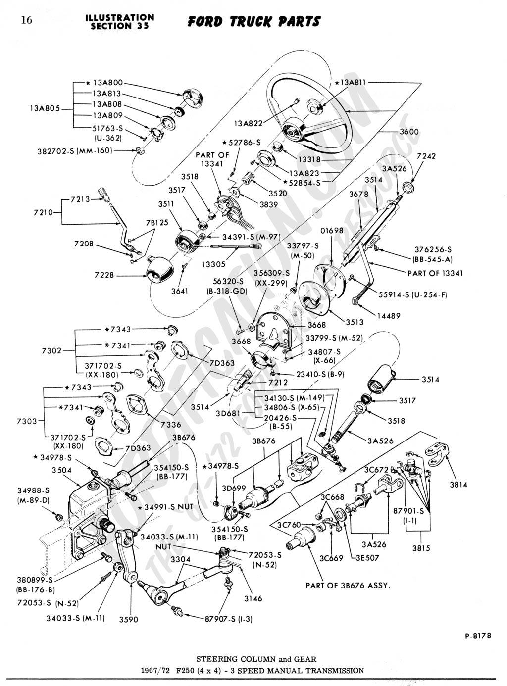
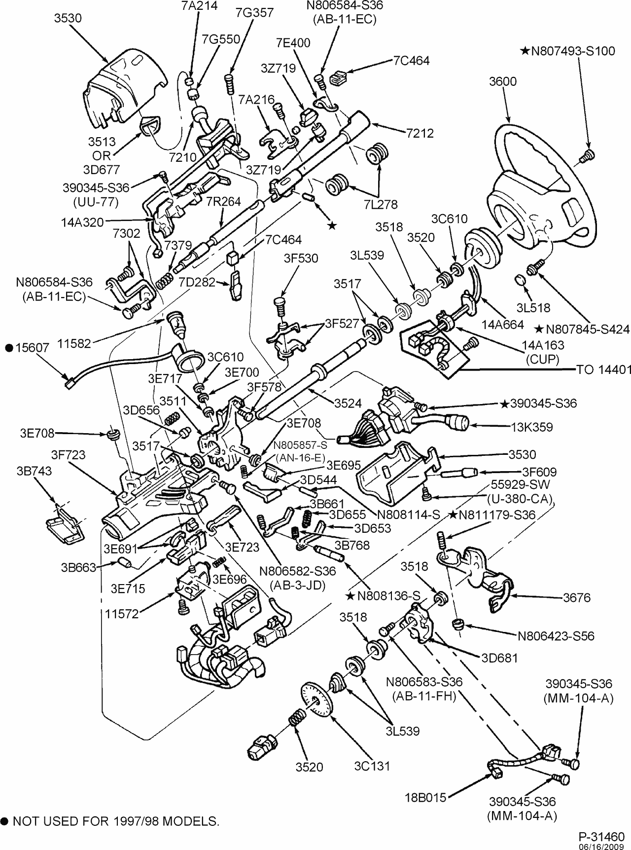
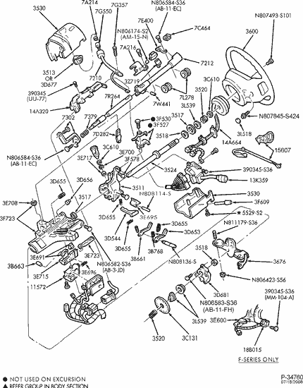
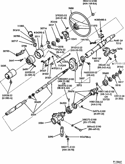
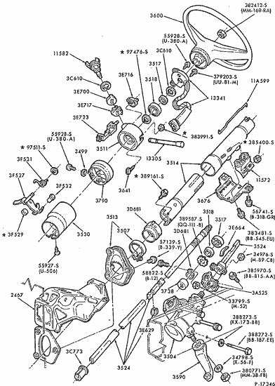
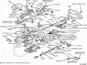 Title : 1989 Ford F 250 Steering Column Diagram Wiring Diagram
Category : Wiring Diagram
Format : PDF
Title : 1989 Ford F 250 Steering Column Diagram Wiring Diagram
Category : Wiring Diagram
Format : PDF