1995-chevy-s10-ignition-wiring-diagram-wiring-diagram.pdf
1 / 90
100%
Download Full Diagram Via this App!!!!
Get Diagram Now! DOWNLOAD NOW
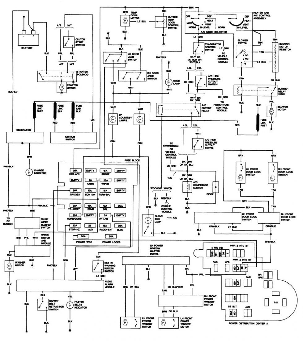
 Title : 1995 Chevy S10 Ignition Wiring Diagram Wiring Diagram
Category : Wiring Diagram
Format : PDF
Title : 1995 Chevy S10 Ignition Wiring Diagram Wiring Diagram
Category : Wiring Diagram
Format : PDF