chevy-s10-pickup-blazer-steering-column-removal-wiring-diagram.pdf
1 / 99
100%
Download Full Diagram Via this App!!!!
Get Diagram Now! DOWNLOAD NOW
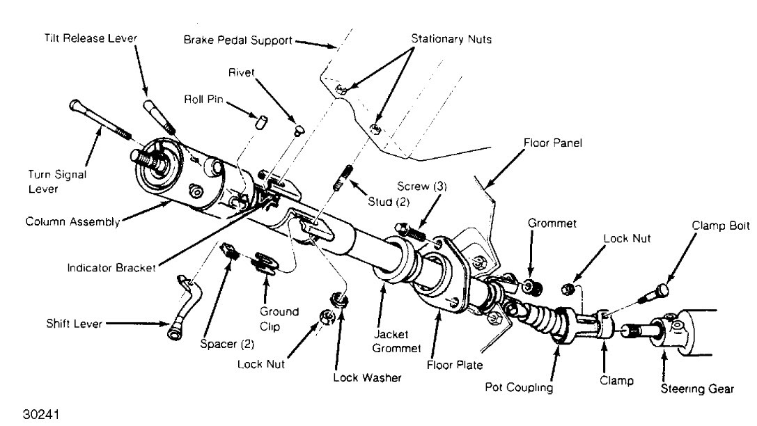
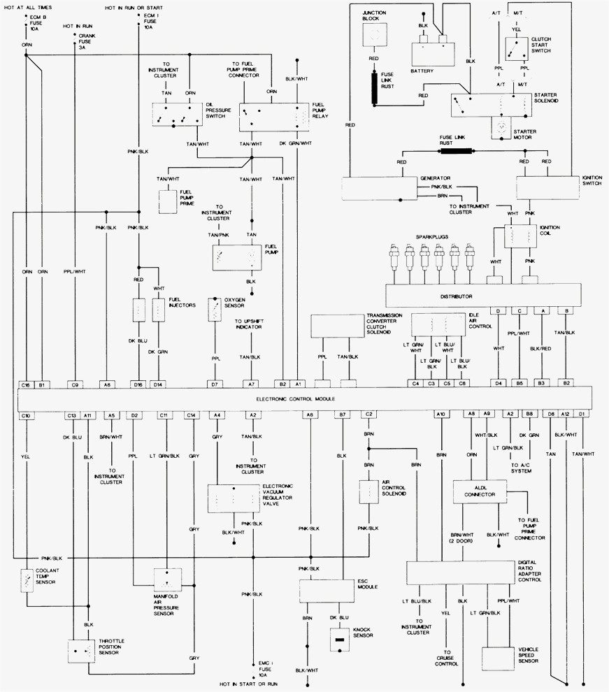
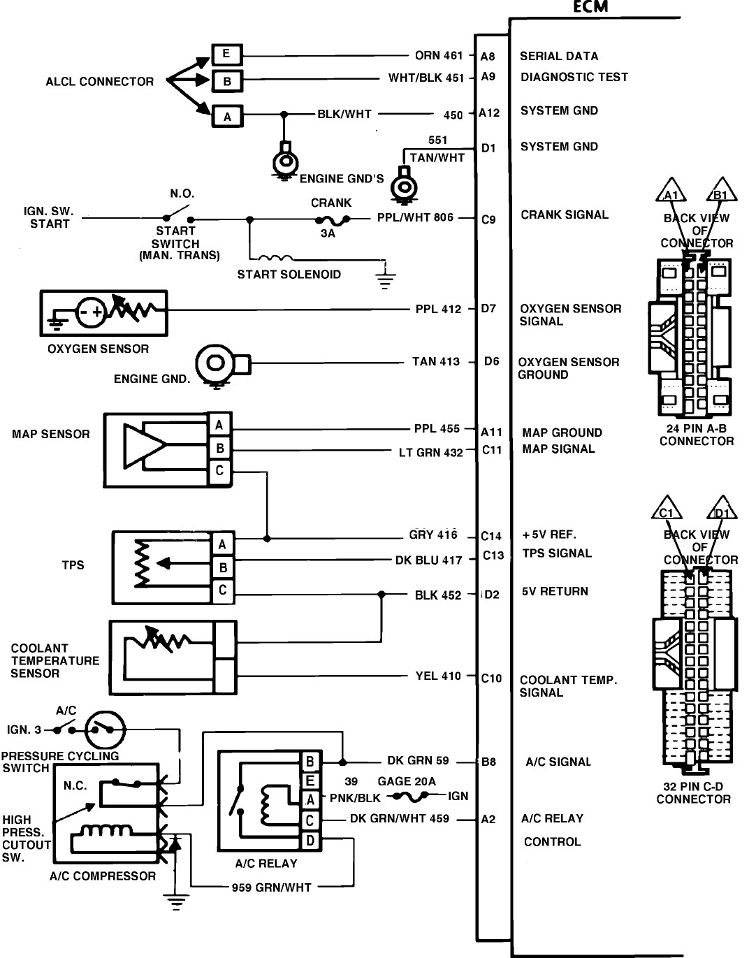
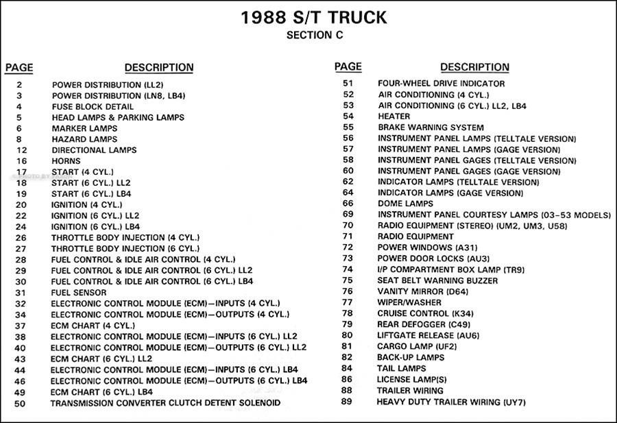
 Title : Chevy S10 Pickup Blazer Steering Column Removal Wiring Diagram
Category : Wiring Diagram
Format : PDF
Title : Chevy S10 Pickup Blazer Steering Column Removal Wiring Diagram
Category : Wiring Diagram
Format : PDF