clark-forklift-starter-wiring-diagram.pdf
1 / 92
100%
Download Full Diagram Via this App!!!!
Get Diagram Now! DOWNLOAD NOW
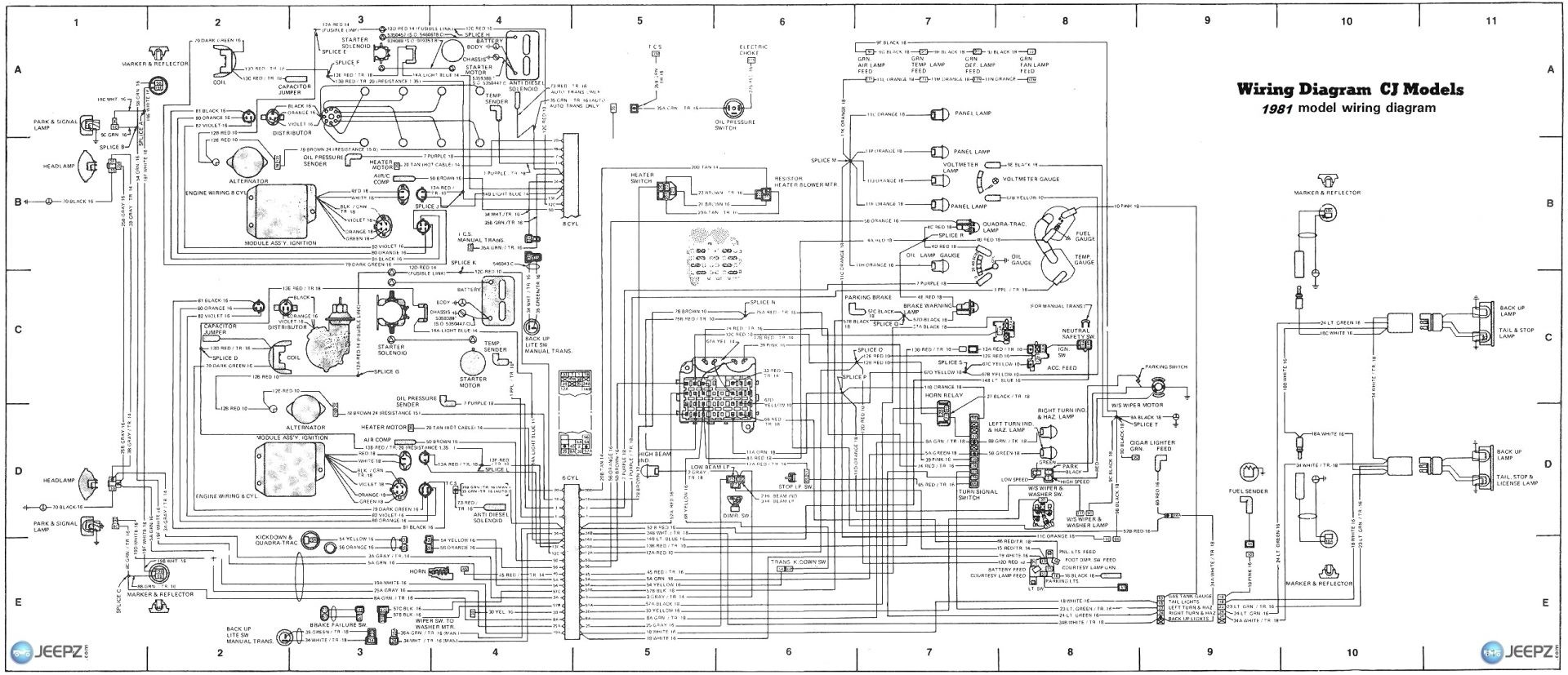
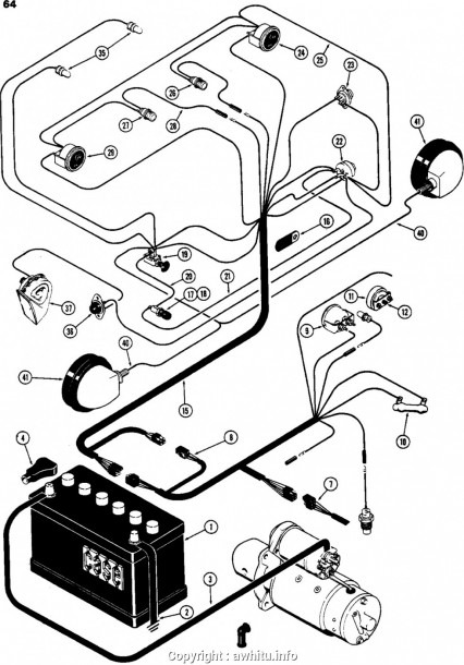
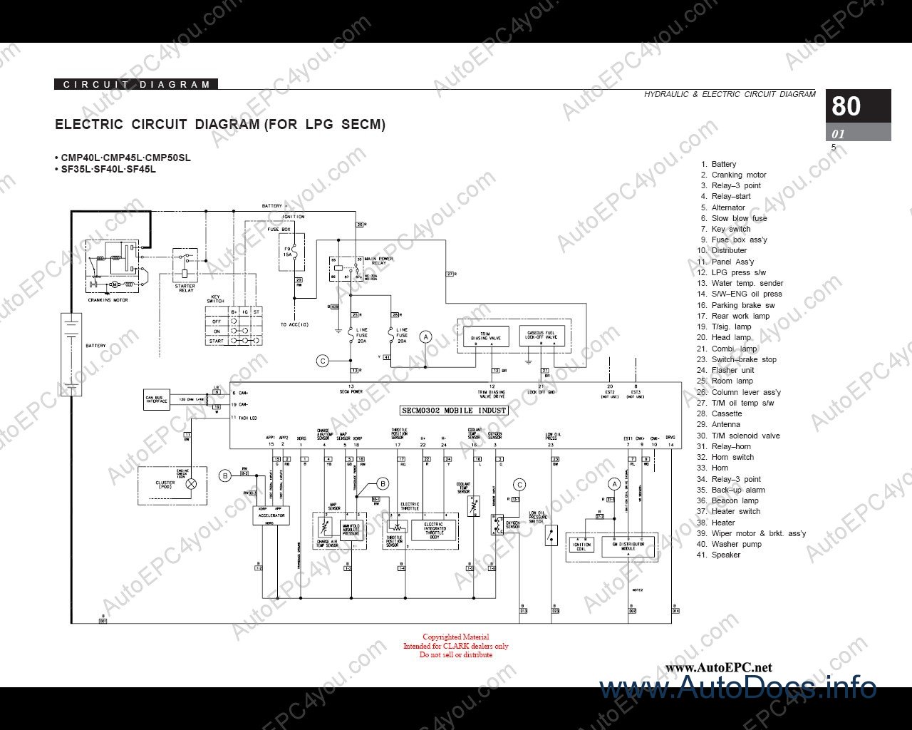
 Title : Clark Forklift Starter Wiring Diagram
Category : Wiring Diagram
Format : PDF
Title : Clark Forklift Starter Wiring Diagram
Category : Wiring Diagram
Format : PDF