defy-built-in-double-oven-black-model-dbo436-wiring-diagram.pdf
1 / 98
100%
Download Full Diagram Via this App!!!!
Get Diagram Now! DOWNLOAD NOW
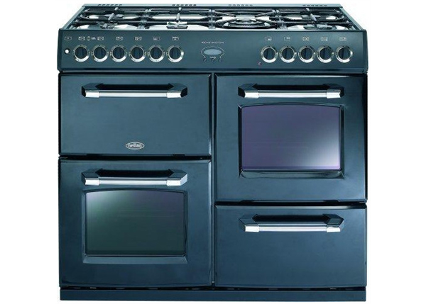
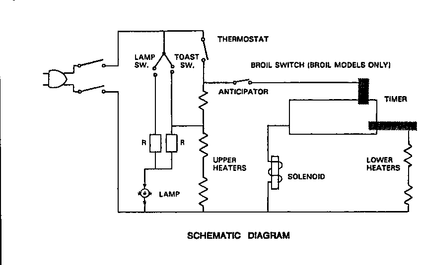
 Title : Defy Built In Double Oven Black Model Dbo436 Wiring Diagram
Category : Wiring Diagram
Format : PDF
Title : Defy Built In Double Oven Black Model Dbo436 Wiring Diagram
Category : Wiring Diagram
Format : PDF