defy-gemini-masterchef-multifunction-thermofan-manual-wiring-diagram.pdf
1 / 98
100%
Download Full Diagram Via this App!!!!
Get Diagram Now! DOWNLOAD NOW
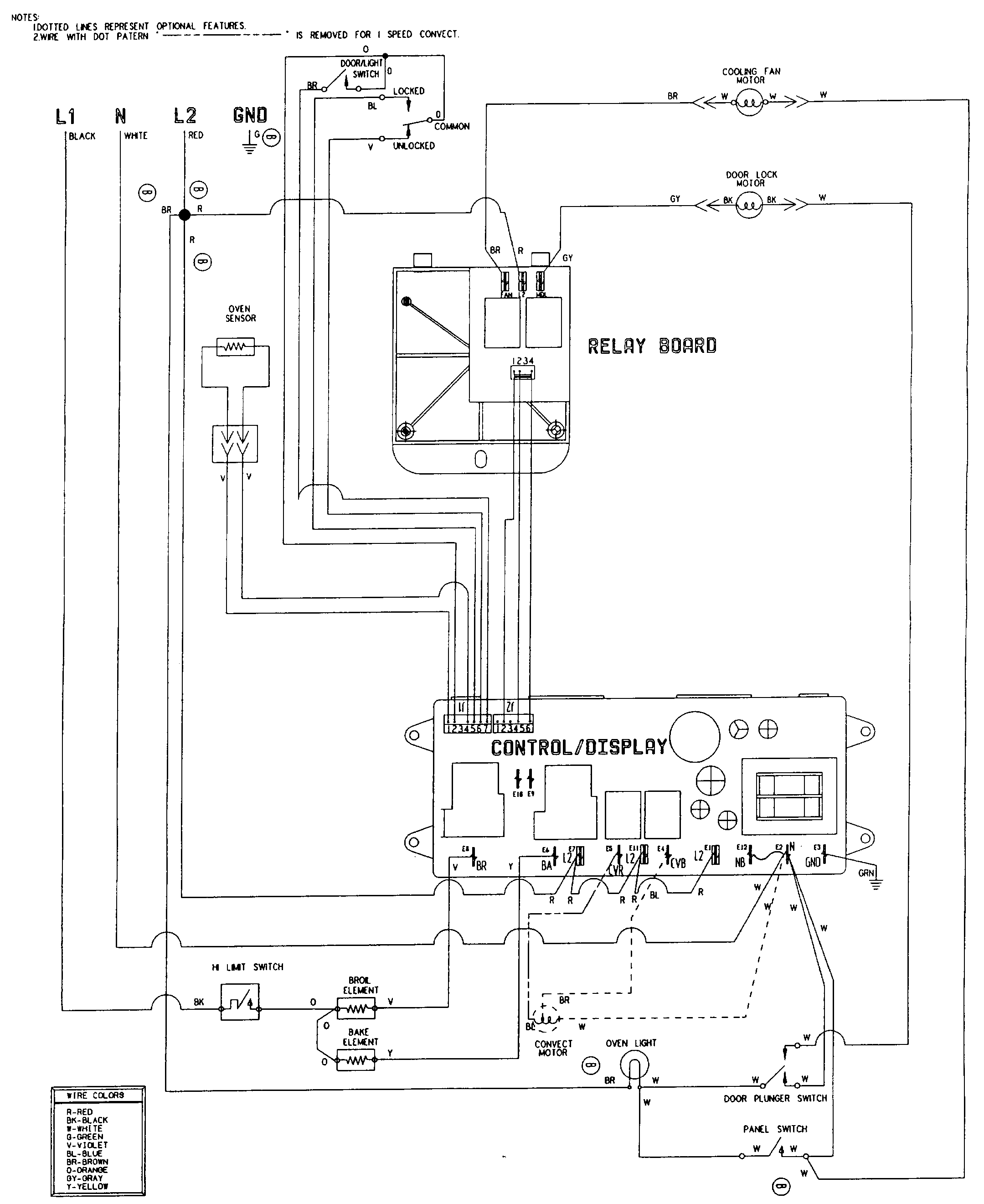
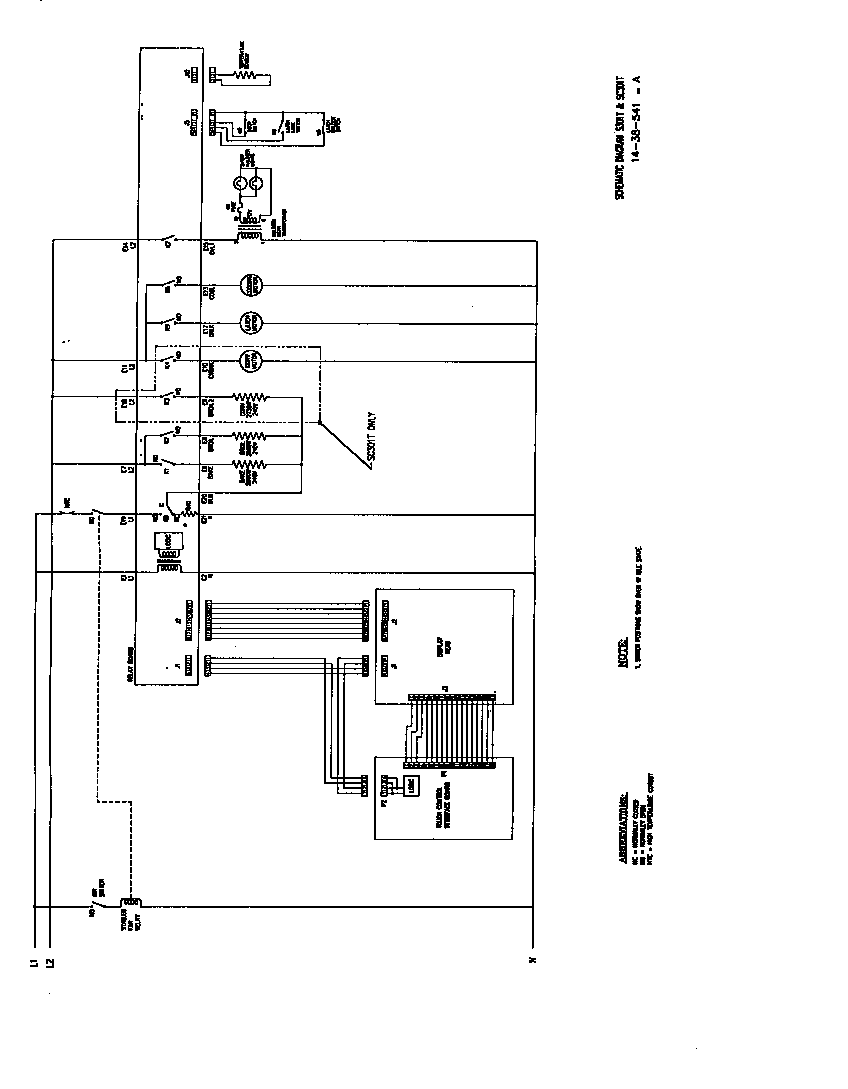
 Title : Defy Gemini Masterchef Multifunction Thermofan Manual Wiring Diagram
Category : Wiring Diagram
Format : PDF
Title : Defy Gemini Masterchef Multifunction Thermofan Manual Wiring Diagram
Category : Wiring Diagram
Format : PDF