defy-slimline-600s-oven-wiring-diagram-wiring-diagram.pdf
1 / 86
100%
Download Full Diagram Via this App!!!!
Get Diagram Now! DOWNLOAD NOW
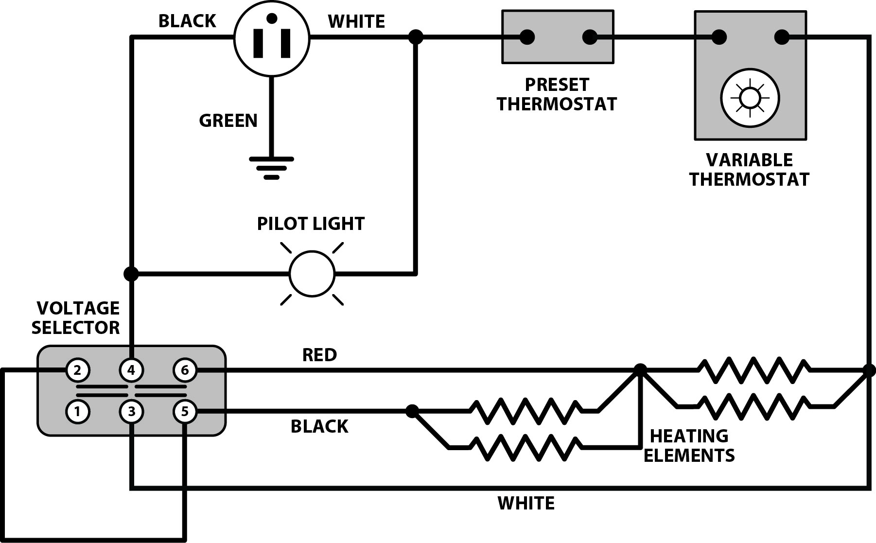
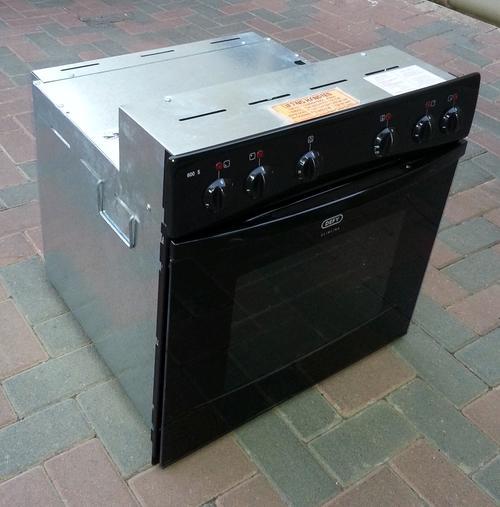
 Title : Defy Slimline 600s Oven Wiring Diagram Wiring Diagram
Category : Wiring Diagram
Format : PDF
Title : Defy Slimline 600s Oven Wiring Diagram Wiring Diagram
Category : Wiring Diagram
Format : PDF