electric-oven-thermostat-wiring-diagram-fantastic-oven-wiring-diagram.pdf
1 / 96
100%
Download Full Diagram Via this App!!!!
Get Diagram Now! DOWNLOAD NOW
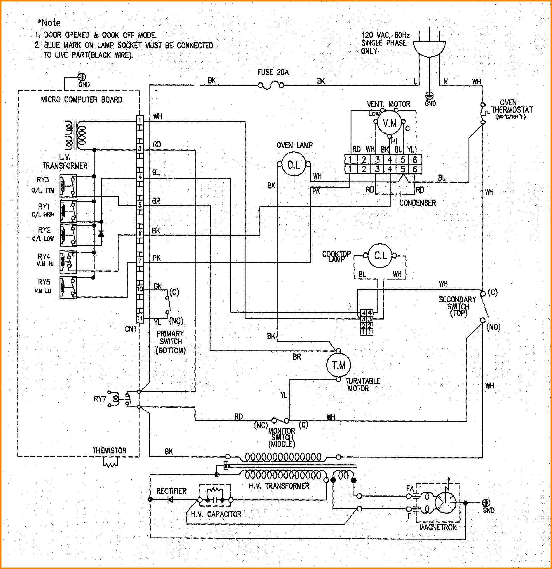
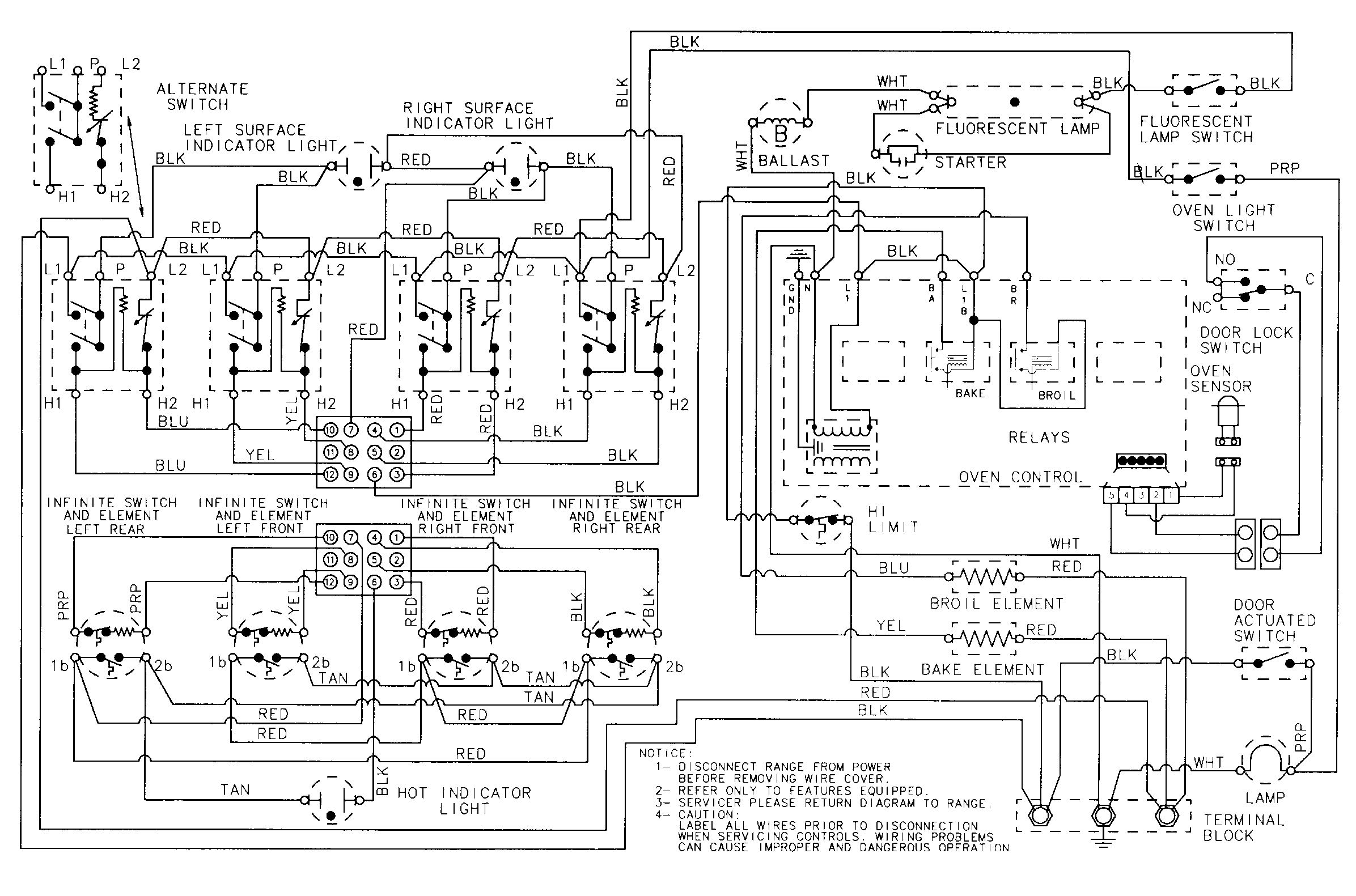
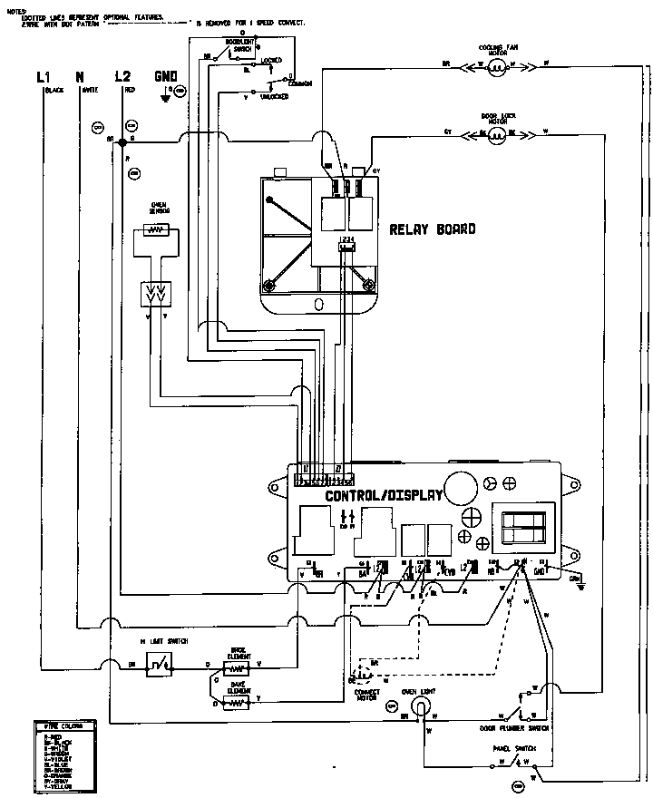
 Title : Electric Oven Thermostat Wiring Diagram Fantastic Oven Wiring Diagram
Category : Wiring Diagram
Format : PDF
Title : Electric Oven Thermostat Wiring Diagram Fantastic Oven Wiring Diagram
Category : Wiring Diagram
Format : PDF