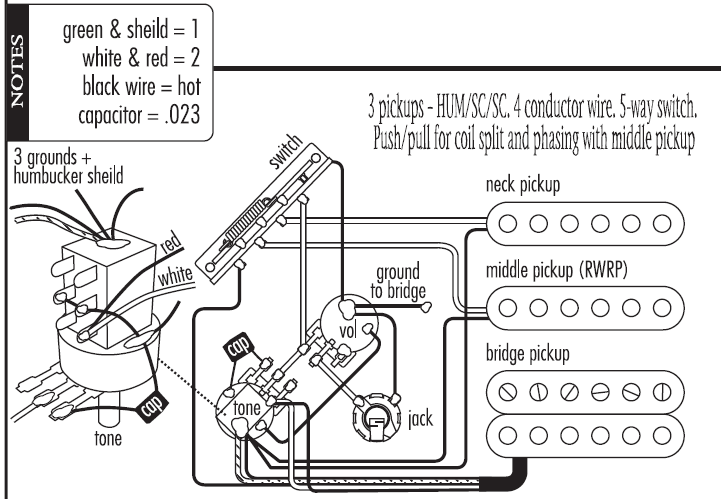
epiphone-by-gibson-les-paul-custom-korea-1990s-wiring-diagram.pdf
100%

Epiphone By Gibson Les Paul Custom Korea 1990s Wiring Diagram


HTTP://WIRINGSCHEMA.COM
Revision 2.6 (02/2016)
© 2016 HTTP://WIRINGSCHEMA.COM. All Rights Reserved.

TABLE OF CONTENTS

Cover1
Table of Contents2
Introduction & Scope3
Safety and Handling4
Symbols & Abbreviations5
Wire Colors & Gauges6
Power Distribution Overview7
Grounding Strategy8
Connector Index & Pinout9
Sensor Inputs10
Actuator Outputs11
Control Unit / Module12
Communication Bus13
Protection: Fuse & Relay14
Test Points & References15
Measurement Procedures16
Troubleshooting Guide17
Common Fault Patterns18
Maintenance & Best Practices19
Appendix & References20
Deep Dive #1 - Signal Integrity & EMC21
Deep Dive #2 - Signal Integrity & EMC22
Deep Dive #3 - Signal Integrity & EMC23
Deep Dive #4 - Signal Integrity & EMC24
Deep Dive #5 - Signal Integrity & EMC25
Deep Dive #6 - Signal Integrity & EMC26
Harness Layout Variant #127
Harness Layout Variant #228
Harness Layout Variant #329
Harness Layout Variant #430
Diagnostic Flowchart #131
Diagnostic Flowchart #232
Diagnostic Flowchart #333
Diagnostic Flowchart #434
Case Study #1 - Real-World Failure35
Case Study #2 - Real-World Failure36
Case Study #3 - Real-World Failure37
Case Study #4 - Real-World Failure38
Case Study #5 - Real-World Failure39
Case Study #6 - Real-World Failure40
Hands-On Lab #1 - Measurement Practice41
Hands-On Lab #2 - Measurement Practice42
Hands-On Lab #3 - Measurement Practice43
Hands-On Lab #4 - Measurement Practice44
Hands-On Lab #5 - Measurement Practice45
Hands-On Lab #6 - Measurement Practice46
Checklist & Form #1 - Quality Verification47
Checklist & Form #2 - Quality Verification48
Checklist & Form #3 - Quality Verification49
Checklist & Form #4 - Quality Verification50
Introduction & Scope Page 3

Contemporary wiring networks depend on advanced methods of power distribution and protection that go far beyond simple wires and fuses. As demands grow, so do the expectations for reliability, speed, and accuracy in supplying voltage to every load. From automotive and aerospace, understanding advanced distribution concepts is foundational for designing and maintaining systems that operate reliably under all conditions.

At its essence, power distribution is the process of transmitting power from a single source to multiple destinations without excessive loss or imbalance. Traditional systems relied on electromechanical devices to manage power. While reliable for decades, these methods struggle when facing dynamic modern loads. To meet new operational standards, engineers now employ electronic circuit breakers, digital fuses and smart sensors, and adaptive electronic protection that respond instantly to load variations.

An digital fuse performs the same function as a conventional one but with precision control. Instead of melting metal, it uses sensors to cut current instantly, often within fractions of a millisecond. Many e-fuses reset automatically after the fault clears, eliminating manual replacement. Advanced versions also report data via industrial communication buses, sharing status and fault history for deeper insight.

MOSFET switches have replaced electromechanical relays in many modern embedded applications. They operate silently, create minimal EMI, and suffer no mechanical wear. In environments subject to shock and harsh conditions, solid-state components surpass mechanical types. However, they introduce thermal challenges, since MOSFETs dissipate power under heavy load. Engineers mitigate this through careful design and cooling integration.

A properly designed power network separates high-current, medium-voltage, and low-power subsystems. Main feeders use copper rails and conductors, branching into localized subnets protected by distributed e-fuse modules. Each node balances between safety and uptime: too lax, and fire risk rises; too tight, and circuits shut down unnecessarily. Smart systems use adaptive thresholds that distinguish temporary surges from actual faults.

Grounding and return-path design form the invisible backbone of modern power networks. Multiple groundslogic, high-current, and safetymust remain isolated yet balanced. Poor grounding causes noise, voltage drift, or false readings. To prevent this, engineers implement star or single-point grounding, using low-impedance connections that maintain stability under vibration. Control units and sensors now monitor ground integrity in real time to detect early degradation or corrosion.

The fusion of electronics and power systems marks a major shift in energy control. Microcontrollers within electronic fuse panels measure real-time loads, log data, and coordinate switching. This intelligence enables data-driven reliability, where systems detect circuits nearing overload. Supervisory software visualizes current paths, fuse status, and system health across entire installations.

Protection components themselves have evolved. In addition to e-fuses, engineers employ self-resetting thermistors and magnetic-trip protection. Polyfuses self-limit current, resetting automatically after coolingideal for space-constrained electronics. Current-limiting breakers trip fast enough to cap energy before conductors overheat. Selection depends on application voltage, current, and duty cycle.

Modern simulation tools enable engineers to simulate current paths and protection timing before hardware is built. By analyzing electrical and thermal interactions, they ensure safe power margins under all conditions. These digital models lead to predictable, safe systems.

From a maintenance view, smart distribution simplifies troubleshooting and monitoring. Built-in sensors and logs record overcurrent events, pinpoint fault locations, and allow virtual reconnection without physical access. This is invaluable in vehicles, aircraft, and offshore systems, reducing manual intervention.

Despite new technologies, the principles remain timeless: electricity must flow efficiently, safely, and controllably. Whether through busbars or MOSFET arrays, each design must ensure proper current path, contain failures fast, and maintain traceable schematics.

In the bigger picture, advanced distribution and modern fusing techniques represent the evolution of classical wiring. They show how hardware and firmware now combine to form adaptive systems that are not only secure but also self-aware and self-correcting. Through these innovations, engineers balance reliability with intelligence, ensuring that energy continues to flow stably and safely.

Figure 1
Safety and Handling Page 4

Electrical safety starts well before you physically touch a conductor. Study the schematic and verify the system’s voltage level. Cut off the primary feed and label it clearly so no one turns it back on. Always have another trained person nearby when working on high-energy equipment. Proper lighting, dry surroundings, and a stable surface prevent most accidental injuries.

Handling techniques define the difference between a temporary repair and a lasting installation. Use insulated, correctly sized pliers and cutters for the exact wire gauge. Be careful not to notch the conductor while stripping, because that weak spot can arc or corrode. Route low-level signal wires far from heavy current cables to limit electromagnetic noise. Neat harness routing is not just cosmetic — it delivers durability and easier service.

When you’re done, run continuity and insulation-resistance tests. Check for exposed filaments, split insulation, or half-clicked connectors. Put every guard and cover back in place before applying power. Real safety is the routine discipline that keeps you, your team, and the equipment safe.

Figure 2
Symbols & Abbreviations Page 5

Understanding symbols and short tags is the key to reading any wiring schematic or service sheet. Instead of long descriptions, electrical systems use standardized icons and short labels to represent power sources, grounds, sensors, actuators, and communication lines. For instance, the ground symbol shows the current return path, and relay/coil symbols indicate where control happens.

Abbreviations are used to compress long terms into a few characters. Typical short forms are VCC (power feed), GND (return reference), SIG (signal path), PWM (duty‑cycle control), CAN (bus), and ECU (module). Parts are tagged with codes like R12, C7, D4 so techs can track individual resistors, capacitors, and diodes during troubleshooting.

Always start by checking the legend that explains the symbol set used in that specific manual. Different brands and industries tweak symbols and shorthands, so never assume the meaning is identical between diagrams. A wrong interpretation can put voltage on a data-only pin and destroy parts; that risk is real when servicing “Epiphone By Gibson Les Paul Custom Korea 1990s Wiring Diagram” hardware in Wiring Diagram. Use this reference responsibly in 2025 and preserve safety requirements documented by http://wiringschema.com.

Figure 3
Wire Colors & Gauges Page 6

The combination of wire colors and gauges forms the language of every electrical circuit. {Each color provides identification for function — such as voltage supply, ground, or communication — while gauge defines how much current it can carry safely.|Colors serve as immediate fun...

Most manufacturers in Wiring Diagram apply international rules such as ISO 6722, SAE J1128, or IEC 60228 when assigning wire color and cross-section size. {Red typically indicates battery voltage, black or brown ground, yellow ignition, ...

When performing maintenance or modification on “Epiphone By Gibson Les Paul Custom Korea 1990s Wiring Diagram”, always match both color and gauge exactly as specified in the service documentation. {Substituting the wrong color can cause confusion for future technicians and violates quality assurance pol...

Figure 4
Power Distribution Overview Page 7

Power distribution refers to the structured process of directing electricity from a central source to various circuits.
It maintains consistent power delivery so that all parts of “Epiphone By Gibson Les Paul Custom Korea 1990s Wiring Diagram” operate with the right voltage and amperage.
An inadequate layout may result in electrical noise, overheating, and unpredictable system failures.
A well-balanced distribution system maintains stable voltage and protects components from electrical overloads.
Hence, power distribution serves as the core framework enabling stable and secure system performance.

Building a high-quality power distribution system requires careful planning and adherence to engineering standards.
Every wire, fuse, and relay must be chosen based on the total electrical load, environmental conditions, and expected duty cycle.
Engineers in Wiring Diagram typically follow ISO 16750, IEC 61000, and SAE J1113 to ensure consistent safety and performance.
Cables carrying large currents should be placed separately from signal or communication lines to prevent interference.
Label and position fuses and relays so they’re easy to find and maintain.
By following these design rules, “Epiphone By Gibson Les Paul Custom Korea 1990s Wiring Diagram” can operate efficiently and reliably under all conditions.

After installation, proper testing and documentation validate that the design performs as required.
They must measure continuity, confirm voltage regulation, and test safety mechanisms for accuracy.
All layout changes should be updated in schematics and logged digitally for traceability.
All test results and supporting files must be archived in http://wiringschema.com for reference and review.
Attaching 2025 and https://http://wiringschema.com/epiphone-by-gibson-les-paul-custom-korea-1990s-wiring-diagram/ provides transparent maintenance history for future checks.
Proper testing and recordkeeping help “Epiphone By Gibson Les Paul Custom Korea 1990s Wiring Diagram” stay durable, efficient, and regulation-compliant.

Figure 5
Grounding Strategy Page 8

Grounding is one of the most essential components in any electrical infrastructure, ensuring protection from faults and system instability.
It provides a direct electrical connection between equipment and the earth, allowing excess current to flow safely away.
A lack of grounding in “Epiphone By Gibson Les Paul Custom Korea 1990s Wiring Diagram” can lead to power spikes, instability, and serious electrical risks.
A well-implemented grounding design ensures voltage balance, operational safety, and longer equipment lifespan.
In Wiring Diagram, grounding is a standard safety requirement that must be maintained throughout the system’s lifetime.

Designing effective grounding requires analyzing soil properties, current paths, and external factors.
Connections should be tight, corrosion-resistant, and built to withstand temperature and moisture variations.
In Wiring Diagram, engineers commonly refer to IEC 60364 and IEEE 142 as the primary standards for grounding and earthing systems.
Each conductor must support maximum current flow safely and prevent excessive heat buildup.
All metallic parts of the system should be bonded to the grounding network to prevent voltage potential differences.
By applying these practices, “Epiphone By Gibson Les Paul Custom Korea 1990s Wiring Diagram” achieves consistent safety, reduced interference, and superior system performance.

Testing and maintenance play a crucial role in preserving grounding effectiveness over time.
Technicians should measure ground resistance, inspect electrode conditions, and confirm mechanical integrity.
Detected defects or corrosion should be fixed immediately and retested for accuracy.
Inspection and maintenance data must be accurately recorded and stored for future audits.
Yearly or post-upgrade testing verifies grounding safety and performance standards.
By maintaining inspection routines, “Epiphone By Gibson Les Paul Custom Korea 1990s Wiring Diagram” ensures long-term safety and operational reliability.

Figure 6
Connector Index & Pinout Page 9

Epiphone By Gibson Les Paul Custom Korea 1990s Wiring Diagram Full Manual – Connector Index & Pinout 2025

Regularly testing connectors verifies that circuits operate as designed. {Technicians typically perform voltage drop, resistance, or continuity tests to confirm proper connection quality.|A simple continuity or voltage check can quickly reveal open or shorted circuits.|By measuring voltage and resistance, faults like corrosion or loose pins can ...

Visual inspection should precede electrical measurement to identify bent or oxidized terminals. Use only manufacturer-approved testing probes and back-probe from the wire side when possible.

Accurate connector testing ensures that each wire delivers the correct signal or voltage. {Documenting test results and connector conditions also helps track performance trends over time.|Technicians should log connector test data for future diagnostic reference.|Recording voltage and resistance readings supports predictive ...

Figure 7
Sensor Inputs Page 10

Epiphone By Gibson Les Paul Custom Korea 1990s Wiring Diagram Wiring Guide – Sensor Inputs 2025

This input is crucial for brake light control, cruise deactivation, and safety systems like ABS or ESC. {When the pedal is pressed, the sensor changes its resistance or voltage output.|The ECU uses this information to trigger braking-related functions and system coordination.|Accurate BPP data ensures immediate response ...

There are two main types of brake pedal sensors: analog potentiometer and digital Hall-effect. {Some advanced systems use dual-circuit sensors for redundancy and fail-safe operation.|Dual outputs allow comparison between channels for error detection.|This redundancy improves reliability in safety-critical...

Common symptoms of a faulty BPP sensor include stuck brake lights, warning codes, or disabled cruise control. {Maintaining BPP sensor function ensures safety compliance and reliable braking communication.|Proper calibration prevents misinterpretation of brake input by the control unit.|Understanding BPP sensor feedback enhances diagnostic pre...

Figure 8
Actuator Outputs Page 11

Epiphone By Gibson Les Paul Custom Korea 1990s Wiring Diagram – Sensor Inputs Reference 2025

APP sensors measure pedal travel to control throttle opening in electronic throttle systems. {It replaces traditional throttle cables with electronic signals that connect the pedal to the throttle body.|By eliminating mechanical linkage, APP systems improve response and reduce maintenance.|Electronic throttle control (ET...

If discrepancies occur, the ECU triggers a fault mode to prevent unintended acceleration. These signals directly influence throttle valve position through motor control.

Technicians should monitor live data and verify signal correlation between channels. {Maintaining APP sensor integrity ensures smooth throttle response and safe vehicle operation.|Proper calibration and diagnostics improve system reliability and drivability.|Understanding APP signal processing helps technicians fine-tune performance an...

Figure 9
Control Unit / Module Page 12

Epiphone By Gibson Les Paul Custom Korea 1990s Wiring Diagram – Actuator Outputs Reference 2025

A stepper motor divides full rotation into equal steps, providing exact position control. {Each step corresponds to a specific angular displacement determined by motor design.|The ECU or controller sends sequential pulse signals to drive the motor coil phases.|By controlling pulse timing and order, the motor achieves accurate pos...

Bipolar stepper motors provide higher torque and efficiency but require H-bridge control. Their design provides inherent position accuracy without needing encoders.

Common stepper control techniques include full-step, half-step, and microstepping. Understanding control sequence and polarity ensures proper motor response and reliability.

Figure 10
Communication Bus Page 13

Communication bus systems in Epiphone By Gibson Les Paul Custom Korea 1990s Wiring Diagram 2025 Wiring Diagram serve as the
coordinated digital backbone that links sensors, actuators, and
electronic control units into a synchronized data environment. Through
structured packet transmission, these networks maintain consistency
across powertrain, chassis, and body domains even under demanding
operating conditions such as thermal expansion, vibration, and
high-speed load transitions.

High-speed CAN governs engine timing, ABS
logic, traction strategies, and other subsystems that require real-time
message exchange, while LIN handles switches and comfort electronics.
FlexRay supports chassis-level precision, and Ethernet transports camera
and radar data with minimal latency.

Communication failures may arise from impedance drift, connector
oxidation, EMI bursts, or degraded shielding, often manifesting as
intermittent sensor dropouts, delayed actuator behavior, or corrupted
frames. Diagnostics require voltage verification, termination checks,
and waveform analysis to isolate the failing segment.

Figure 11
Protection: Fuse & Relay Page 14

Protection systems in Epiphone By Gibson Les Paul Custom Korea 1990s Wiring Diagram 2025 Wiring Diagram rely on fuses and relays
to form a controlled barrier between electrical loads and the vehicle’s
power distribution backbone. These elements react instantly to abnormal
current patterns, stopping excessive amperage before it cascades into
critical modules. By segmenting circuits into isolated branches, the
system protects sensors, control units, lighting, and auxiliary
equipment from thermal stress and wiring burnout.

In modern architectures, relays handle repetitive activation
cycles, executing commands triggered by sensors or control software.
Their isolation capabilities reduce stress on low‑current circuits,
while fuses provide sacrificial protection whenever load spikes exceed
tolerance thresholds. Together they create a multi‑layer defense grid
adaptable to varying thermal and voltage demands.

Technicians often
diagnose issues by tracking inconsistent current delivery, noisy relay
actuation, unusual voltage fluctuations, or thermal discoloration on
fuse panels. Addressing these problems involves cleaning terminals,
reseating connectors, conditioning ground paths, and confirming load
consumption through controlled testing. Maintaining relay responsiveness
and fuse integrity ensures long‑term electrical stability.

Figure 12
Test Points & References Page 15

Within modern automotive systems, reference
pads act as structured anchor locations for buffered signal channels,
enabling repeatable and consistent measurement sessions. Their placement
across sensor returns, control-module feeds, and distribution junctions
ensures that technicians can evaluate baseline conditions without
interference from adjacent circuits. This allows diagnostic tools to
interpret subsystem health with greater accuracy.

Using their strategic layout, test points enable buffered
signal channels, ensuring that faults related to thermal drift,
intermittent grounding, connector looseness, or voltage instability are
detected with precision. These checkpoints streamline the
troubleshooting workflow by eliminating unnecessary inspection of
unrelated harness branches and focusing attention on the segments most
likely to generate anomalies.

Frequent discoveries made at reference nodes
involve irregular waveform signatures, contact oxidation, fluctuating
supply levels, and mechanical fatigue around connector bodies.
Diagnostic procedures include load simulation, voltage-drop mapping, and
ground potential verification to ensure that each subsystem receives
stable and predictable electrical behavior under all operating
conditions.

Figure 13
Measurement Procedures Page 16

In modern systems,
structured diagnostics rely heavily on module-return signal tracing,
allowing technicians to capture consistent reference data while
minimizing interference from adjacent circuits. This structured approach
improves accuracy when identifying early deviations or subtle electrical
irregularities within distributed subsystems.

Technicians utilize these measurements to evaluate waveform stability,
sensor-output verification, and voltage behavior across multiple
subsystem domains. Comparing measured values against specifications
helps identify root causes such as component drift, grounding
inconsistencies, or load-induced fluctuations.

Common measurement findings include fluctuating supply rails, irregular
ground returns, unstable sensor signals, and waveform distortion caused
by EMI contamination. Technicians use oscilloscopes, multimeters, and
load probes to isolate these anomalies with precision.

Figure 14
Troubleshooting Guide Page 17

Troubleshooting for Epiphone By Gibson Les Paul Custom Korea 1990s Wiring Diagram 2025 Wiring Diagram begins with generalized
subsystem checks, ensuring the diagnostic process starts with clarity
and consistency. By checking basic system readiness, technicians avoid
deeper misinterpretations.

Field testing
incorporates live-data interpretation routines, providing insight into
conditions that may not appear during bench testing. This highlights
environment‑dependent anomalies.

Degraded shielding may allow external electromagnetic bursts to distort
communication lines. Shield continuity checks and rewrapping harness
segments mitigate the issue.

Figure 15
Common Fault Patterns Page 18

Across diverse vehicle architectures, issues related to
cross-talk interference from adjacent high-current lines represent a
dominant source of unpredictable faults. These faults may develop
gradually over months of thermal cycling, vibrations, or load
variations, ultimately causing operational anomalies that mimic
unrelated failures. Effective troubleshooting requires technicians to
start with a holistic overview of subsystem behavior, forming accurate
expectations about what healthy signals should look like before
proceeding.

Patterns
linked to cross-talk interference from adjacent high-current lines
frequently reveal themselves during active subsystem transitions, such
as ignition events, relay switching, or electronic module
initialization. The resulting irregularities—whether sudden voltage
dips, digital noise pulses, or inconsistent ground offset—are best
analyzed using waveform-capture tools that expose micro-level
distortions invisible to simple multimeter checks.

Persistent problems associated with cross-talk interference from
adjacent high-current lines can escalate into module desynchronization,
sporadic sensor lockups, or complete loss of communication on shared
data lines. Technicians must examine wiring paths for mechanical
fatigue, verify grounding architecture stability, assess connector
tension, and confirm that supply rails remain steady across temperature
changes. Failure to address these foundational issues often leads to
repeated return visits.

Figure 16
Maintenance & Best Practices Page 19

Maintenance and best practices for Epiphone By Gibson Les Paul Custom Korea 1990s Wiring Diagram 2025 Wiring Diagram place
strong emphasis on insulation health verification procedures, ensuring
that electrical reliability remains consistent across all operating
conditions. Technicians begin by examining the harness environment,
verifying routing paths, and confirming that insulation remains intact.
This foundational approach prevents intermittent issues commonly
triggered by heat, vibration, or environmental contamination.

Technicians
analyzing insulation health verification procedures typically monitor
connector alignment, evaluate oxidation levels, and inspect wiring for
subtle deformations caused by prolonged thermal exposure. Protective
dielectric compounds and proper routing practices further contribute to
stable electrical pathways that resist mechanical stress and
environmental impact.

Failure
to maintain insulation health verification procedures can lead to
cascading electrical inconsistencies, including voltage drops, sensor
signal distortion, and sporadic subsystem instability. Long-term
reliability requires careful documentation, periodic connector service,
and verification of each branch circuit’s mechanical and electrical
health under both static and dynamic conditions.

Figure 17
Appendix & References Page 20

The appendix for Epiphone By Gibson Les Paul Custom Korea 1990s Wiring Diagram 2025 Wiring Diagram serves as a consolidated
reference hub focused on color‑coding reference for multi‑branch
harnesses, offering technicians consistent terminology and structured
documentation practices. By collecting technical descriptors,
abbreviations, and classification rules into a single section, the
appendix streamlines interpretation of wiring layouts across diverse
platforms. This ensures that even complex circuit structures remain
approachable through standardized definitions and reference cues.

Documentation related to color‑coding reference for multi‑branch
harnesses frequently includes structured tables, indexing lists, and
lookup summaries that reduce the need to cross‑reference multiple
sources during system evaluation. These entries typically describe
connector types, circuit categories, subsystem identifiers, and signal
behavior definitions. By keeping these details accessible, technicians
can accelerate the interpretation of wiring diagrams and troubleshoot
with greater accuracy.

Comprehensive references for color‑coding reference for multi‑branch
harnesses also support long‑term documentation quality by ensuring
uniform terminology across service manuals, schematics, and diagnostic
tools. When updates occur—whether due to new sensors, revised standards,
or subsystem redesigns—the appendix remains the authoritative source for
maintaining alignment between engineering documentation and real‑world
service practices.

Figure 18
Deep Dive #1 - Signal Integrity & EMC Page 21

Deep analysis of signal integrity in Epiphone By Gibson Les Paul Custom Korea 1990s Wiring Diagram 2025 Wiring Diagram requires
investigating how shielding degradation from mechanical fatigue disrupts
expected waveform performance across interconnected circuits. As signals
propagate through long harnesses, subtle distortions accumulate due to
impedance shifts, parasitic capacitance, and external electromagnetic
stress. This foundational assessment enables technicians to understand
where integrity loss begins and how it evolves.

When shielding degradation from mechanical fatigue occurs, signals may
experience phase delays, amplitude decay, or transient ringing depending
on harness composition and environmental exposure. Technicians must
review waveform transitions under varying thermal, load, and EMI
conditions. Tools such as high‑bandwidth oscilloscopes and frequency
analyzers reveal distortion patterns that remain hidden during static
measurements.

Left uncorrected, shielding degradation from mechanical fatigue can
progress into widespread communication degradation, module
desynchronization, or unstable sensor logic. Technicians must verify
shielding continuity, examine grounding symmetry, analyze differential
paths, and validate signal behavior across environmental extremes. Such
comprehensive evaluation ensures repairs address root EMC
vulnerabilities rather than surface‑level symptoms.

Figure 19
Deep Dive #2 - Signal Integrity & EMC Page 22

Deep technical assessment of EMC interactions must account for
near-field coupling from high‑current switching devices, as the
resulting disturbances can propagate across wiring networks and disrupt
timing‑critical communication. These disruptions often appear
sporadically, making early waveform sampling essential to characterize
the extent of electromagnetic influence across multiple operational
states.

When near-field coupling from high‑current switching devices is
present, it may introduce waveform skew, in-band noise, or pulse
deformation that impacts the accuracy of both analog and digital
subsystems. Technicians must examine behavior under load, evaluate the
impact of switching events, and compare multi-frequency responses.
High‑resolution oscilloscopes and field probes reveal distortion
patterns hidden in time-domain measurements.

If left unresolved, near-field coupling from high‑current
switching devices may trigger cascading disruptions including frame
corruption, false sensor readings, and irregular module coordination.
Effective countermeasures include controlled grounding, noise‑filter
deployment, re‑termination of critical paths, and restructuring of cable
routing to minimize electromagnetic coupling.

Figure 20
Deep Dive #3 - Signal Integrity & EMC Page 23

A comprehensive
assessment of waveform stability requires understanding the effects of
conducted surges from auxiliary accessories disrupting ECU timing, a
factor capable of reshaping digital and analog signal profiles in subtle
yet impactful ways. This initial analysis phase helps technicians
identify whether distortions originate from physical harness geometry,
electromagnetic ingress, or internal module reference instability.

Systems experiencing conducted surges from auxiliary
accessories disrupting ECU timing often show dynamic fluctuations during
transitions such as relay switching, injector activation, or alternator
charging ramps. These transitions inject complex disturbances into
shared wiring paths, making it essential to perform frequency-domain
inspection, spectral decomposition, and transient-load waveform sampling
to fully characterize the EMC interaction.

Prolonged exposure to conducted surges from auxiliary accessories
disrupting ECU timing may result in cumulative timing drift, erratic
communication retries, or persistent sensor inconsistencies. Mitigation
strategies include rebalancing harness impedance, reinforcing shielding
layers, deploying targeted EMI filters, optimizing grounding topology,
and refining cable routing to minimize exposure to EMC hotspots. These
measures restore signal clarity and long-term subsystem reliability.

Figure 21
Deep Dive #4 - Signal Integrity & EMC Page 24

Evaluating advanced signal‑integrity interactions involves
examining the influence of reflected‑energy accumulation from partial
harness terminations, a phenomenon capable of inducing significant
waveform displacement. These disruptions often develop gradually,
becoming noticeable only when communication reliability begins to drift
or subsystem timing loses coherence.

When reflected‑energy accumulation from partial harness terminations is
active, waveform distortion may manifest through amplitude instability,
reference drift, unexpected ringing artifacts, or shifting propagation
delays. These effects often correlate with subsystem transitions,
thermal cycles, actuator bursts, or environmental EMI fluctuations.
High‑bandwidth test equipment reveals the microscopic deviations hidden
within normal signal envelopes.

If unresolved, reflected‑energy
accumulation from partial harness terminations may escalate into severe
operational instability, corrupting digital frames or disrupting
tight‑timing control loops. Effective mitigation requires targeted
filtering, optimized termination schemes, strategic rerouting, and
harmonic suppression tailored to the affected frequency bands.

Figure 22
Deep Dive #5 - Signal Integrity & EMC Page 25

Advanced waveform diagnostics in Epiphone By Gibson Les Paul Custom Korea 1990s Wiring Diagram 2025 Wiring Diagram must account
for lossy‑media propagation degrading analog sensor fidelity, a complex
interaction that reshapes both analog and digital signal behavior across
interconnected subsystems. As modern vehicle architectures push higher
data rates and consolidate multiple electrical domains, even small EMI
vectors can distort timing, amplitude, and reference stability.

When lossy‑media propagation degrading analog sensor fidelity is
active, signal paths may exhibit ringing artifacts, asymmetric edge
transitions, timing drift, or unexpected amplitude compression. These
effects are amplified during actuator bursts, ignition sequencing, or
simultaneous communication surges. Technicians rely on high-bandwidth
oscilloscopes and spectral analysis to characterize these distortions
accurately.

If left
unresolved, lossy‑media propagation degrading analog sensor fidelity may
evolve into severe operational instability—ranging from data corruption
to sporadic ECU desynchronization. Effective countermeasures include
refining harness geometry, isolating radiated hotspots, enhancing
return-path uniformity, and implementing frequency-specific suppression
techniques.

Figure 23
Deep Dive #6 - Signal Integrity & EMC Page 26

Advanced EMC analysis in Epiphone By Gibson Les Paul Custom Korea 1990s Wiring Diagram 2025 Wiring Diagram must consider
battery-pack switching transients disturbing high-speed communication
PHY layers, a complex interaction capable of reshaping waveform
integrity across numerous interconnected subsystems. As modern vehicles
integrate high-speed communication layers, ADAS modules, EV power
electronics, and dense mixed-signal harness routing, even subtle
non-linear effects can disrupt deterministic timing and system
reliability.

When battery-pack switching transients disturbing high-speed
communication PHY layers occurs, technicians may observe inconsistent
rise-times, amplitude drift, complex ringing patterns, or intermittent
jitter artifacts. These symptoms often appear during subsystem
interactions—such as inverter ramps, actuator bursts, ADAS
synchronization cycles, or ground-potential fluctuations. High-bandwidth
oscilloscopes and spectrum analyzers reveal hidden distortion
signatures.

If unresolved,
battery-pack switching transients disturbing high-speed communication
PHY layers can escalate into catastrophic failure modes—ranging from
module resets and actuator misfires to complete subsystem
desynchronization. Effective corrective actions include tuning impedance
profiles, isolating radiated hotspots, applying frequency-specific
suppression, and refining communication topology to ensure long-term
stability.

Figure 24
Harness Layout Variant #1 Page 27

Designing Epiphone By Gibson Les Paul Custom Korea 1990s Wiring Diagram 2025 Wiring Diagram harness layouts requires close
evaluation of shielding‑zone alignment for sensitive sensor wiring, an
essential factor that influences both electrical performance and
mechanical longevity. Because harnesses interact with multiple vehicle
structures—panels, brackets, chassis contours—designers must ensure that
routing paths accommodate thermal expansion, vibration profiles, and
accessibility for maintenance.

Field performance often
depends on how effectively designers addressed shielding‑zone alignment
for sensitive sensor wiring. Variations in cable elevation, distance
from noise sources, and branch‑point sequencing can amplify or mitigate
EMI exposure, mechanical fatigue, and access difficulties during
service.

Unchecked, shielding‑zone alignment for sensitive sensor wiring
may lead to premature insulation wear, intermittent electrical noise,
connector stress, or routing interference with moving components.
Implementing balanced tensioning, precise alignment, service-friendly
positioning, and clear labeling mitigates long-term risk and enhances
system maintainability.

Figure 25
Harness Layout Variant #2 Page 28

Harness Layout Variant #2 for Epiphone By Gibson Les Paul Custom Korea 1990s Wiring Diagram 2025 Wiring Diagram focuses on
power–data spacing rules for long parallel paths, a structural and
electrical consideration that influences both reliability and long-term
stability. As modern vehicles integrate more electronic modules, routing
strategies must balance physical constraints with the need for
predictable signal behavior.

In real-world conditions, power–data spacing rules for long
parallel paths determines the durability of the harness against
temperature cycles, motion-induced stress, and subsystem interference.
Careful arrangement of connectors, bundling layers, and anti-chafe
supports helps maintain reliable performance even in high-demand chassis
zones.

Managing power–data spacing rules for long parallel paths effectively
results in improved robustness, simplified maintenance, and enhanced
overall system stability. Engineers apply isolation rules, structural
reinforcement, and optimized routing logic to produce a layout capable
of sustaining long-term operational loads.

Figure 26
Harness Layout Variant #3 Page 29

Harness Layout Variant #3 for Epiphone By Gibson Les Paul Custom Korea 1990s Wiring Diagram 2025 Wiring Diagram focuses on
anti‑fatigue routing crimps for long-path power distribution, an
essential structural and functional element that affects reliability
across multiple vehicle zones. Modern platforms require routing that
accommodates mechanical constraints while sustaining consistent
electrical behavior and long-term durability.

During refinement, anti‑fatigue routing crimps for long-path power
distribution can impact vibration resistance, shielding effectiveness,
ground continuity, and stress distribution along key segments. Designers
analyze bundle thickness, elevation shifts, structural transitions, and
separation from high‑interference components to optimize both mechanical
and electrical performance.

Managing anti‑fatigue routing crimps for long-path power distribution
effectively ensures robust, serviceable, and EMI‑resistant harness
layouts. Engineers rely on optimized routing classifications, grounding
structures, anti‑wear layers, and anchoring intervals to produce a
layout that withstands long-term operational loads.

Figure 27
Harness Layout Variant #4 Page 30

The architectural
approach for this variant prioritizes sensor-cluster star-topology breakouts for diagnostics, focusing on
service access, electrical noise reduction, and long-term durability. Engineers balance bundle compactness
with proper signal separation to avoid EMI coupling while keeping the routing footprint efficient.

In real-world operation,
sensor-cluster star-topology breakouts for diagnostics affects signal quality near actuators, motors, and
infotainment modules. Cable elevation, branch sequencing, and anti-chafe barriers reduce premature wear. A
combination of elastic tie-points, protective sleeves, and low-profile clips keeps bundles orderly yet
flexible under dynamic loads.

Proper control of sensor-cluster star-topology breakouts for diagnostics
minimizes moisture intrusion, terminal corrosion, and cross-path noise. Best practices include labeled
manufacturing references, measured service loops, and HV/LV clearance audits. When components are updated,
route documentation and measurement points simplify verification without dismantling the entire assembly.

Figure 28
Diagnostic Flowchart #1 Page 31

Diagnostic Flowchart #1 for Epiphone By Gibson Les Paul Custom Korea 1990s Wiring Diagram 2025 Wiring Diagram begins with tiered diagnostic branching for complex
multi‑module faults, establishing a precise entry point that helps technicians determine whether symptoms
originate from signal distortion, grounding faults, or early‑stage communication instability. A consistent
diagnostic baseline prevents unnecessary part replacement and improves accuracy. As diagnostics progress, tiered diagnostic branching for complex multi‑module faults becomes a
critical branch factor influencing decisions relating to grounding integrity, power sequencing, and network
communication paths. This structured logic ensures accuracy even when symptoms appear scattered. A complete
validation cycle ensures tiered diagnostic branching for complex multi‑module faults is confirmed across all
operational states. Documenting each decision point creates traceability, enabling faster future diagnostics
and reducing the chance of repeat failures.

Figure 29
Diagnostic Flowchart #2 Page 32

Diagnostic Flowchart #2 for Epiphone By Gibson Les Paul Custom Korea 1990s Wiring Diagram 2025 Wiring Diagram begins by addressing conditional module reset testing
under controlled load, establishing a clear entry point for isolating electrical irregularities that may
appear intermittent or load‑dependent. Technicians rely on this structured starting node to avoid
misinterpretation of symptoms caused by secondary effects. Throughout the flowchart, conditional module reset testing under controlled load interacts with
verification procedures involving reference stability, module synchronization, and relay or fuse behavior.
Each decision point eliminates entire categories of possible failures, allowing the technician to converge
toward root cause faster. If conditional module reset testing under controlled load is not thoroughly examined, intermittent
signal distortion or cascading electrical faults may remain hidden. Reinforcing each decision node with
precise measurement steps prevents misdiagnosis and strengthens long-term reliability.

Figure 30
Diagnostic Flowchart #3 Page 33

The first branch of Diagnostic Flowchart #3 prioritizes latency‑shift analysis during Ethernet
frame bursts, ensuring foundational stability is confirmed before deeper subsystem exploration. This prevents
misdirection caused by intermittent or misleading electrical behavior. As the flowchart progresses,
latency‑shift analysis during Ethernet frame bursts defines how mid‑stage decisions are segmented. Technicians
sequentially eliminate power, ground, communication, and actuation domains while interpreting timing shifts,
signal drift, or misalignment across related circuits. Once latency‑shift analysis during Ethernet frame bursts is fully evaluated across multiple load
states, the technician can confirm or dismiss entire fault categories. This structured approach enhances
long‑term reliability and reduces repeat troubleshooting visits.

Figure 31
Diagnostic Flowchart #4 Page 34

Diagnostic Flowchart #4 for Epiphone By Gibson Les Paul Custom Korea 1990s Wiring Diagram 2025 Wiring Diagram focuses on PWM‑signal distortion analysis across
actuator paths, laying the foundation for a structured fault‑isolation path that eliminates guesswork and
reduces unnecessary component swapping. The first stage examines core references, voltage stability, and
baseline communication health to determine whether the issue originates in the primary network layer or in a
secondary subsystem. Technicians follow a branched decision flow that evaluates signal symmetry, grounding
patterns, and frame stability before advancing into deeper diagnostic layers. As the evaluation continues, PWM‑signal distortion analysis across
actuator paths becomes the controlling factor for mid‑level branch decisions. This includes correlating
waveform alignment, identifying momentary desync signatures, and interpreting module wake‑timing conflicts. By
dividing the diagnostic pathway into focused electrical domains—power delivery, grounding integrity,
communication architecture, and actuator response—the flowchart ensures that each stage removes entire
categories of faults with minimal overlap. This structured segmentation accelerates troubleshooting and
increases diagnostic precision. The final stage ensures that PWM‑signal distortion analysis across actuator paths is validated
under multiple operating conditions, including thermal stress, load spikes, vibration, and state transitions.
These controlled stress points help reveal hidden instabilities that may not appear during static testing.
Completing all verification nodes ensures long‑term stability, reducing the likelihood of recurring issues and
enabling technicians to document clear, repeatable steps for future diagnostics.

Figure 32
Case Study #1 - Real-World Failure Page 35

Case Study #1 for Epiphone By Gibson Les Paul Custom Korea 1990s Wiring Diagram 2025 Wiring Diagram examines a real‑world failure involving body‑control module
wake‑logic failure caused by timing drift. The issue first appeared as an intermittent symptom that did not
trigger a consistent fault code, causing technicians to suspect unrelated components. Early observations
highlighted irregular electrical behavior, such as momentary signal distortion, delayed module responses, or
fluctuating reference values. These symptoms tended to surface under specific thermal, vibration, or load
conditions, making replication difficult during static diagnostic tests. Further investigation into
body‑control module wake‑logic failure caused by timing drift required systematic measurement across power
distribution paths, grounding nodes, and communication channels. Technicians used targeted diagnostic
flowcharts to isolate variables such as voltage drop, EMI exposure, timing skew, and subsystem
desynchronization. By reproducing the fault under controlled conditions—applying heat, inducing vibration, or
simulating high load—they identified the precise moment the failure manifested. This structured process
eliminated multiple potential contributors, narrowing the fault domain to a specific harness segment,
component group, or module logic pathway. The confirmed cause tied to body‑control module wake‑logic failure
caused by timing drift allowed technicians to implement the correct repair, whether through component
replacement, harness restoration, recalibration, or module reprogramming. After corrective action, the system
was subjected to repeated verification cycles to ensure long‑term stability under all operating conditions.
Documenting the failure pattern and diagnostic sequence provided valuable reference material for similar
future cases, reducing diagnostic time and preventing unnecessary part replacement.

Figure 33
Case Study #2 - Real-World Failure Page 36

Case Study #2 for Epiphone By Gibson Les Paul Custom Korea 1990s Wiring Diagram 2025 Wiring Diagram examines a real‑world failure involving dual‑sensor disagreement
caused by thermal drift in a hall‑effect pair. The issue presented itself with intermittent symptoms that
varied depending on temperature, load, or vehicle motion. Technicians initially observed irregular system
responses, inconsistent sensor readings, or sporadic communication drops. Because the symptoms did not follow
a predictable pattern, early attempts at replication were unsuccessful, leading to misleading assumptions
about unrelated subsystems. A detailed investigation into dual‑sensor disagreement caused by thermal drift in
a hall‑effect pair required structured diagnostic branching that isolated power delivery, ground stability,
communication timing, and sensor integrity. Using controlled diagnostic tools, technicians applied thermal
load, vibration, and staged electrical demand to recreate the failure in a measurable environment. Progressive
elimination of subsystem groups—ECUs, harness segments, reference points, and actuator pathways—helped reveal
how the failure manifested only under specific operating thresholds. This systematic breakdown prevented
misdiagnosis and reduced unnecessary component swaps. Once the cause linked to dual‑sensor disagreement
caused by thermal drift in a hall‑effect pair was confirmed, the corrective action involved either
reconditioning the harness, replacing the affected component, reprogramming module firmware, or adjusting
calibration parameters. Post‑repair validation cycles were performed under varied conditions to ensure
long‑term reliability and prevent future recurrence. Documentation of the failure characteristics, diagnostic
sequence, and final resolution now serves as a reference for addressing similar complex faults more
efficiently.

Figure 34
Case Study #3 - Real-World Failure Page 37

Case Study #3 for Epiphone By Gibson Les Paul Custom Korea 1990s Wiring Diagram 2025 Wiring Diagram focuses on a real‑world failure involving dual‑path sensor
disagreement created by uneven heat distribution. Technicians first observed erratic system behavior,
including fluctuating sensor values, delayed control responses, and sporadic communication warnings. These
symptoms appeared inconsistently, often only under specific temperature, load, or vibration conditions. Early
troubleshooting attempts failed to replicate the issue reliably, creating the impression of multiple unrelated
subsystem faults rather than a single root cause. To investigate dual‑path sensor disagreement created by
uneven heat distribution, a structured diagnostic approach was essential. Technicians conducted staged power
and ground validation, followed by controlled stress testing that included thermal loading, vibration
simulation, and alternating electrical demand. This method helped reveal the precise operational threshold at
which the failure manifested. By isolating system domains—communication networks, power rails, grounding
nodes, and actuator pathways—the diagnostic team progressively eliminated misleading symptoms and narrowed the
problem to a specific failure mechanism. After identifying the underlying cause tied to dual‑path sensor
disagreement created by uneven heat distribution, technicians carried out targeted corrective actions such as
replacing compromised components, restoring harness integrity, updating ECU firmware, or recalibrating
affected subsystems. Post‑repair validation cycles confirmed stable performance across all operating
conditions. The documented diagnostic path and resolution now serve as a repeatable reference for addressing
similar failures with greater speed and accuracy.

Figure 35
Case Study #4 - Real-World Failure Page 38

Case Study #4 for Epiphone By Gibson Les Paul Custom Korea 1990s Wiring Diagram 2025 Wiring Diagram examines a high‑complexity real‑world failure involving
multi‑module cascade failure initiated by fluctuating body‑ground potentials. The issue manifested across
multiple subsystems simultaneously, creating an array of misleading symptoms ranging from inconsistent module
responses to distorted sensor feedback and intermittent communication warnings. Initial diagnostics were
inconclusive due to the fault’s dependency on vibration, thermal shifts, or rapid load changes. These
fluctuating conditions allowed the failure to remain dormant during static testing, pushing technicians to
explore deeper system interactions that extended beyond conventional troubleshooting frameworks. To
investigate multi‑module cascade failure initiated by fluctuating body‑ground potentials, technicians
implemented a layered diagnostic workflow combining power‑rail monitoring, ground‑path validation, EMI
tracing, and logic‑layer analysis. Stress tests were applied in controlled sequences to recreate the precise
environment in which the instability surfaced—often requiring synchronized heat, vibration, and electrical
load modulation. By isolating communication domains, verifying timing thresholds, and comparing analog sensor
behavior under dynamic conditions, the diagnostic team uncovered subtle inconsistencies that pointed toward
deeper system‑level interactions rather than isolated component faults. After confirming the root mechanism
tied to multi‑module cascade failure initiated by fluctuating body‑ground potentials, corrective action
involved component replacement, harness reconditioning, ground‑plane reinforcement, or ECU firmware
restructuring depending on the failure’s nature. Technicians performed post‑repair endurance tests that
included repeated thermal cycling, vibration exposure, and electrical stress to guarantee long‑term system
stability. Thorough documentation of the analysis method, failure pattern, and final resolution now serves as
a highly valuable reference for identifying and mitigating similar high‑complexity failures in the future.

Figure 36
Case Study #5 - Real-World Failure Page 39

Case Study #5 for Epiphone By Gibson Les Paul Custom Korea 1990s Wiring Diagram 2025 Wiring Diagram investigates a complex real‑world failure involving
vibration‑triggered connector lift affecting ignition timing. The issue initially presented as an inconsistent
mixture of delayed system reactions, irregular sensor values, and sporadic communication disruptions. These
events tended to appear under dynamic operational conditions—such as elevated temperatures, sudden load
transitions, or mechanical vibration—which made early replication attempts unreliable. Technicians encountered
symptoms occurring across multiple modules simultaneously, suggesting a deeper systemic interaction rather
than a single isolated component failure. During the investigation of vibration‑triggered connector lift
affecting ignition timing, a multi‑layered diagnostic workflow was deployed. Technicians performed sequential
power‑rail mapping, ground‑plane verification, and high‑frequency noise tracing to detect hidden
instabilities. Controlled stress testing—including targeted heat application, induced vibration, and variable
load modulation—was carried out to reproduce the failure consistently. The team methodically isolated
subsystem domains such as communication networks, analog sensor paths, actuator control logic, and module
synchronization timing. This progressive elimination approach identified critical operational thresholds where
the failure reliably emerged. After determining the underlying mechanism tied to vibration‑triggered
connector lift affecting ignition timing, technicians carried out corrective actions that ranged from harness
reconditioning and connector reinforcement to firmware restructuring and recalibration of affected modules.
Post‑repair validation involved repeated cycles of vibration, thermal stress, and voltage fluctuation to
ensure long‑term stability and eliminate the possibility of recurrence. The documented resolution pathway now
serves as an advanced reference model for diagnosing similarly complex failures across modern vehicle
platforms.

Figure 37
Case Study #6 - Real-World Failure Page 40

Case Study #6 for Epiphone By Gibson Les Paul Custom Korea 1990s Wiring Diagram 2025 Wiring Diagram examines a complex real‑world failure involving nonlinear MAP
sensor collapse during high‑frequency vibration bursts. Symptoms emerged irregularly, with clustered faults
appearing across unrelated modules, giving the impression of multiple simultaneous subsystem failures. These
irregularities depended strongly on vibration, temperature shifts, or abrupt electrical load changes, making
the issue difficult to reproduce during initial diagnostic attempts. Technicians noted inconsistent sensor
feedback, communication delays, and momentary power‑rail fluctuations that persisted without generating
definitive fault codes. The investigation into nonlinear MAP sensor collapse during high‑frequency vibration
bursts required a multi‑layer diagnostic strategy combining signal‑path tracing, ground stability assessment,
and high‑frequency noise evaluation. Technicians executed controlled stress tests—including thermal cycling,
vibration induction, and staged electrical loading—to reveal the exact thresholds at which the fault
manifested. Using structured elimination across harness segments, module clusters, and reference nodes, they
isolated subtle timing deviations, analog distortions, or communication desynchronization that pointed toward
a deeper systemic failure mechanism rather than isolated component malfunction. Once nonlinear MAP sensor
collapse during high‑frequency vibration bursts was identified as the root failure mechanism, targeted
corrective measures were implemented. These included harness reinforcement, connector replacement, firmware
restructuring, recalibration of key modules, or ground‑path reconfiguration depending on the nature of the
instability. Post‑repair endurance runs with repeated vibration, heat cycles, and voltage stress ensured
long‑term reliability. Documentation of the diagnostic sequence and recovery pathway now provides a vital
reference for detecting and resolving similarly complex failures more efficiently in future service
operations.

Figure 38
Hands-On Lab #1 - Measurement Practice Page 41

Hands‑On Lab #1 for Epiphone By Gibson Les Paul Custom Korea 1990s Wiring Diagram 2025 Wiring Diagram focuses on wideband O2 sensor response‑time measurement. This
exercise teaches technicians how to perform structured diagnostic measurements using multimeters,
oscilloscopes, current probes, and differential tools. The initial phase emphasizes establishing a stable
baseline by checking reference voltages, verifying continuity, and confirming ground integrity. These
foundational steps ensure that subsequent measurements reflect true system behavior rather than secondary
anomalies introduced by poor probing technique or unstable electrical conditions. During the measurement
routine for wideband O2 sensor response‑time measurement, technicians analyze dynamic behavior by applying
controlled load, capturing waveform transitions, and monitoring subsystem responses. This includes observing
timing shifts, duty‑cycle changes, ripple patterns, or communication irregularities. By replicating real
operating conditions—thermal changes, vibration, or electrical demand spikes—technicians gain insight into how
the system behaves under stress. This approach allows deeper interpretation of patterns that static readings
cannot reveal. After completing the procedure for wideband O2 sensor response‑time measurement, results are
documented with precise measurement values, waveform captures, and interpretation notes. Technicians compare
the observed data with known good references to determine whether performance falls within acceptable
thresholds. The collected information not only confirms system health but also builds long‑term diagnostic
proficiency by helping technicians recognize early indicators of failure and understand how small variations
can evolve into larger issues.

Figure 39
Hands-On Lab #2 - Measurement Practice Page 42

Hands‑On Lab #2 for Epiphone By Gibson Les Paul Custom Korea 1990s Wiring Diagram 2025 Wiring Diagram focuses on ground path impedance profiling across distributed
modules. This practical exercise expands technician measurement skills by emphasizing accurate probing
technique, stable reference validation, and controlled test‑environment setup. Establishing baseline
readings—such as reference ground, regulated voltage output, and static waveform characteristics—is essential
before any dynamic testing occurs. These foundational checks prevent misinterpretation caused by poor tool
placement, floating grounds, or unstable measurement conditions. During the procedure for ground path
impedance profiling across distributed modules, technicians simulate operating conditions using thermal
stress, vibration input, and staged subsystem loading. Dynamic measurements reveal timing inconsistencies,
amplitude drift, duty‑cycle changes, communication irregularities, or nonlinear sensor behavior.
Oscilloscopes, current probes, and differential meters are used to capture high‑resolution waveform data,
enabling technicians to identify subtle deviations that static multimeter readings cannot detect. Emphasis is
placed on interpreting waveform shape, slope, ripple components, and synchronization accuracy across
interacting modules. After completing the measurement routine for ground path impedance profiling across
distributed modules, technicians document quantitative findings—including waveform captures, voltage ranges,
timing intervals, and noise signatures. The recorded results are compared to known‑good references to
determine subsystem health and detect early‑stage degradation. This structured approach not only builds
diagnostic proficiency but also enhances a technician’s ability to predict emerging faults before they
manifest as critical failures, strengthening long‑term reliability of the entire system.

Figure 40
Hands-On Lab #3 - Measurement Practice Page 43

Hands‑On Lab #3 for Epiphone By Gibson Les Paul Custom Korea 1990s Wiring Diagram 2025 Wiring Diagram focuses on vehicle-ground potential variance tracing across body
points. This exercise trains technicians to establish accurate baseline measurements before introducing
dynamic stress. Initial steps include validating reference grounds, confirming supply‑rail stability, and
ensuring probing accuracy. These fundamentals prevent distorted readings and help ensure that waveform
captures or voltage measurements reflect true electrical behavior rather than artifacts caused by improper
setup or tool noise. During the diagnostic routine for vehicle-ground potential variance tracing across body
points, technicians apply controlled environmental adjustments such as thermal cycling, vibration, electrical
loading, and communication traffic modulation. These dynamic inputs help expose timing drift, ripple growth,
duty‑cycle deviations, analog‑signal distortion, or module synchronization errors. Oscilloscopes, clamp
meters, and differential probes are used extensively to capture transitional data that cannot be observed with
static measurements alone. After completing the measurement sequence for vehicle-ground potential variance
tracing across body points, technicians document waveform characteristics, voltage ranges, current behavior,
communication timing variations, and noise patterns. Comparison with known‑good datasets allows early
detection of performance anomalies and marginal conditions. This structured measurement methodology
strengthens diagnostic confidence and enables technicians to identify subtle degradation before it becomes a
critical operational failure.

Figure 41
Hands-On Lab #4 - Measurement Practice Page 44

Hands‑On Lab #4 for Epiphone By Gibson Les Paul Custom Korea 1990s Wiring Diagram 2025 Wiring Diagram focuses on ABS sensor waveform stability during controlled
deceleration tests. This laboratory exercise builds on prior modules by emphasizing deeper measurement
accuracy, environment control, and test‑condition replication. Technicians begin by validating stable
reference grounds, confirming regulated supply integrity, and preparing measurement tools such as
oscilloscopes, current probes, and high‑bandwidth differential probes. Establishing clean baselines ensures
that subsequent waveform analysis is meaningful and not influenced by tool noise or ground drift. During the
measurement procedure for ABS sensor waveform stability during controlled deceleration tests, technicians
introduce dynamic variations including staged electrical loading, thermal cycling, vibration input, or
communication‑bus saturation. These conditions reveal real‑time behaviors such as timing drift, amplitude
instability, duty‑cycle deviation, ripple formation, or synchronization loss between interacting modules.
High‑resolution waveform capture enables technicians to observe subtle waveform features—slew rate, edge
deformation, overshoot, undershoot, noise bursts, and harmonic artifacts. Upon completing the assessment for
ABS sensor waveform stability during controlled deceleration tests, all findings are documented with waveform
snapshots, quantitative measurements, and diagnostic interpretations. Comparing collected data with verified
reference signatures helps identify early‑stage degradation, marginal component performance, and hidden
instability trends. This rigorous measurement framework strengthens diagnostic precision and ensures that
technicians can detect complex electrical issues long before they evolve into system‑wide failures.

Figure 42
Hands-On Lab #5 - Measurement Practice Page 45

Hands‑On Lab #5 for Epiphone By Gibson Les Paul Custom Korea 1990s Wiring Diagram 2025 Wiring Diagram focuses on Ethernet PHY timing coherence under diagnostic
flooding. The session begins with establishing stable measurement baselines by validating grounding integrity,
confirming supply‑rail stability, and ensuring probe calibration. These steps prevent erroneous readings and
ensure that all waveform captures accurately reflect subsystem behavior. High‑accuracy tools such as
oscilloscopes, clamp meters, and differential probes are prepared to avoid ground‑loop artifacts or
measurement noise. During the procedure for Ethernet PHY timing coherence under diagnostic flooding,
technicians introduce dynamic test conditions such as controlled load spikes, thermal cycling, vibration, and
communication saturation. These deliberate stresses expose real‑time effects like timing jitter, duty‑cycle
deformation, signal‑edge distortion, ripple growth, and cross‑module synchronization drift. High‑resolution
waveform captures allow technicians to identify anomalies that static tests cannot reveal, such as harmonic
noise, high‑frequency interference, or momentary dropouts in communication signals. After completing all
measurements for Ethernet PHY timing coherence under diagnostic flooding, technicians document voltage ranges,
timing intervals, waveform shapes, noise signatures, and current‑draw curves. These results are compared
against known‑good references to identify early‑stage degradation or marginal component behavior. Through this
structured measurement framework, technicians strengthen diagnostic accuracy and develop long‑term proficiency
in detecting subtle trends that could lead to future system failures.

Figure 43
Hands-On Lab #6 - Measurement Practice Page 46

Hands‑On Lab #6 for Epiphone By Gibson Les Paul Custom Korea 1990s Wiring Diagram 2025 Wiring Diagram focuses on ground‑path impedance drift evaluation across body
structural nodes. This advanced laboratory module strengthens technician capability in capturing high‑accuracy
diagnostic measurements. The session begins with baseline validation of ground reference integrity, regulated
supply behavior, and probe calibration. Ensuring noise‑free, stable baselines prevents waveform distortion and
guarantees that all readings reflect genuine subsystem behavior rather than tool‑induced artifacts or
grounding errors. Technicians then apply controlled environmental modulation such as thermal shocks,
vibration exposure, staged load cycling, and communication traffic saturation. These dynamic conditions reveal
subtle faults including timing jitter, duty‑cycle deformation, amplitude fluctuation, edge‑rate distortion,
harmonic buildup, ripple amplification, and module synchronization drift. High‑bandwidth oscilloscopes,
differential probes, and current clamps are used to capture transient behaviors invisible to static multimeter
measurements. Following completion of the measurement routine for ground‑path impedance drift evaluation
across body structural nodes, technicians document waveform shapes, voltage windows, timing offsets, noise
signatures, and current patterns. Results are compared against validated reference datasets to detect
early‑stage degradation or marginal component behavior. By mastering this structured diagnostic framework,
technicians build long‑term proficiency and can identify complex electrical instabilities before they lead to
full system failure.

Figure 44
Checklist & Form #1 - Quality Verification Page 47

Checklist & Form #1 for Epiphone By Gibson Les Paul Custom Korea 1990s Wiring Diagram 2025 Wiring Diagram focuses on network‑latency and arbitration‑timing
verification sheet. This verification document provides a structured method for ensuring electrical and
electronic subsystems meet required performance standards. Technicians begin by confirming baseline conditions
such as stable reference grounds, regulated voltage supplies, and proper connector engagement. Establishing
these baselines prevents false readings and ensures all subsequent measurements accurately reflect system
behavior. During completion of this form for network‑latency and arbitration‑timing verification sheet,
technicians evaluate subsystem performance under both static and dynamic conditions. This includes validating
signal integrity, monitoring voltage or current drift, assessing noise susceptibility, and confirming
communication stability across modules. Checkpoints guide technicians through critical inspection areas—sensor
accuracy, actuator responsiveness, bus timing, harness quality, and module synchronization—ensuring each
element is validated thoroughly using industry‑standard measurement practices. After filling out the
checklist for network‑latency and arbitration‑timing verification sheet, all results are documented,
interpreted, and compared against known‑good reference values. This structured documentation supports
long‑term reliability tracking, facilitates early detection of emerging issues, and strengthens overall system
quality. The completed form becomes part of the quality‑assurance record, ensuring compliance with technical
standards and providing traceability for future diagnostics.

Figure 45
Checklist & Form #2 - Quality Verification Page 48

Checklist & Form #2 for Epiphone By Gibson Les Paul Custom Korea 1990s Wiring Diagram 2025 Wiring Diagram focuses on communication‑bus fault‑resilience verification
form. This structured verification tool guides technicians through a comprehensive evaluation of electrical
system readiness. The process begins by validating baseline electrical conditions such as stable ground
references, regulated supply integrity, and secure connector engagement. Establishing these fundamentals
ensures that all subsequent diagnostic readings reflect true subsystem behavior rather than interference from
setup or tooling issues. While completing this form for communication‑bus fault‑resilience verification form,
technicians examine subsystem performance across both static and dynamic conditions. Evaluation tasks include
verifying signal consistency, assessing noise susceptibility, monitoring thermal drift effects, checking
communication timing accuracy, and confirming actuator responsiveness. Each checkpoint guides the technician
through critical areas that contribute to overall system reliability, helping ensure that performance remains
within specification even during operational stress. After documenting all required fields for
communication‑bus fault‑resilience verification form, technicians interpret recorded measurements and compare
them against validated reference datasets. This documentation provides traceability, supports early detection
of marginal conditions, and strengthens long‑term quality control. The completed checklist forms part of the
official audit trail and contributes directly to maintaining electrical‑system reliability across the vehicle
platform.

Figure 46
Checklist & Form #3 - Quality Verification Page 49

Checklist & Form #3 for Epiphone By Gibson Les Paul Custom Korea 1990s Wiring Diagram 2025 Wiring Diagram covers ripple and transient‑spike tolerance report. This
verification document ensures that every subsystem meets electrical and operational requirements before final
approval. Technicians begin by validating fundamental conditions such as regulated supply voltage, stable
ground references, and secure connector seating. These baseline checks eliminate misleading readings and
ensure that all subsequent measurements represent true subsystem behavior without tool‑induced artifacts.
While completing this form for ripple and transient‑spike tolerance report, technicians review subsystem
behavior under multiple operating conditions. This includes monitoring thermal drift, verifying
signal‑integrity consistency, checking module synchronization, assessing noise susceptibility, and confirming
actuator responsiveness. Structured checkpoints guide technicians through critical categories such as
communication timing, harness integrity, analog‑signal quality, and digital logic performance to ensure
comprehensive verification. After documenting all required values for ripple and transient‑spike tolerance
report, technicians compare collected data with validated reference datasets. This ensures compliance with
design tolerances and facilitates early detection of marginal or unstable behavior. The completed form becomes
part of the permanent quality‑assurance record, supporting traceability, long‑term reliability monitoring, and
efficient future diagnostics.

Figure 47
Checklist & Form #4 - Quality Verification Page 50

Checklist & Form #4 for Epiphone By Gibson Les Paul Custom Korea 1990s Wiring Diagram 2025 Wiring Diagram documents voltage‑drop distribution and tolerance‑mapping
form. This final‑stage verification tool ensures that all electrical subsystems meet operational, structural,
and diagnostic requirements prior to release. Technicians begin by confirming essential baseline conditions
such as reference‑ground accuracy, stabilized supply rails, connector engagement integrity, and sensor
readiness. Proper baseline validation eliminates misleading measurements and guarantees that subsequent
inspection results reflect authentic subsystem behavior. While completing this verification form for
voltage‑drop distribution and tolerance‑mapping form, technicians evaluate subsystem stability under
controlled stress conditions. This includes monitoring thermal drift, confirming actuator consistency,
validating signal integrity, assessing network‑timing alignment, verifying resistance and continuity
thresholds, and checking noise immunity levels across sensitive analog and digital pathways. Each checklist
point is structured to guide the technician through areas that directly influence long‑term reliability and
diagnostic predictability. After completing the form for voltage‑drop distribution and tolerance‑mapping
form, technicians document measurement results, compare them with approved reference profiles, and certify
subsystem compliance. This documentation provides traceability, aids in trend analysis, and ensures adherence
to quality‑assurance standards. The completed form becomes part of the permanent electrical validation record,
supporting reliable operation throughout the vehicle’s lifecycle.

Figure 48