florida-forklift-supply-inc-new-clark-forklift-parts-wiring-diagram.pdf
1 / 90
100%
Download Full Diagram Via this App!!!!
Get Diagram Now! DOWNLOAD NOW
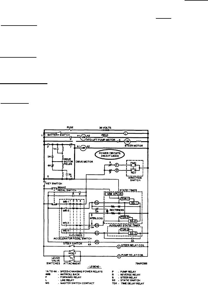
 Title : Florida Forklift Supply Inc New Clark Forklift Parts Wiring Diagram
Category : Wiring Diagram
Format : PDF
Title : Florida Forklift Supply Inc New Clark Forklift Parts Wiring Diagram
Category : Wiring Diagram
Format : PDF