ford-f-250-super-duty-manifold-wiring-diagram.pdf
1 / 94
100%
Download Full Diagram Via this App!!!!
Get Diagram Now! DOWNLOAD NOW
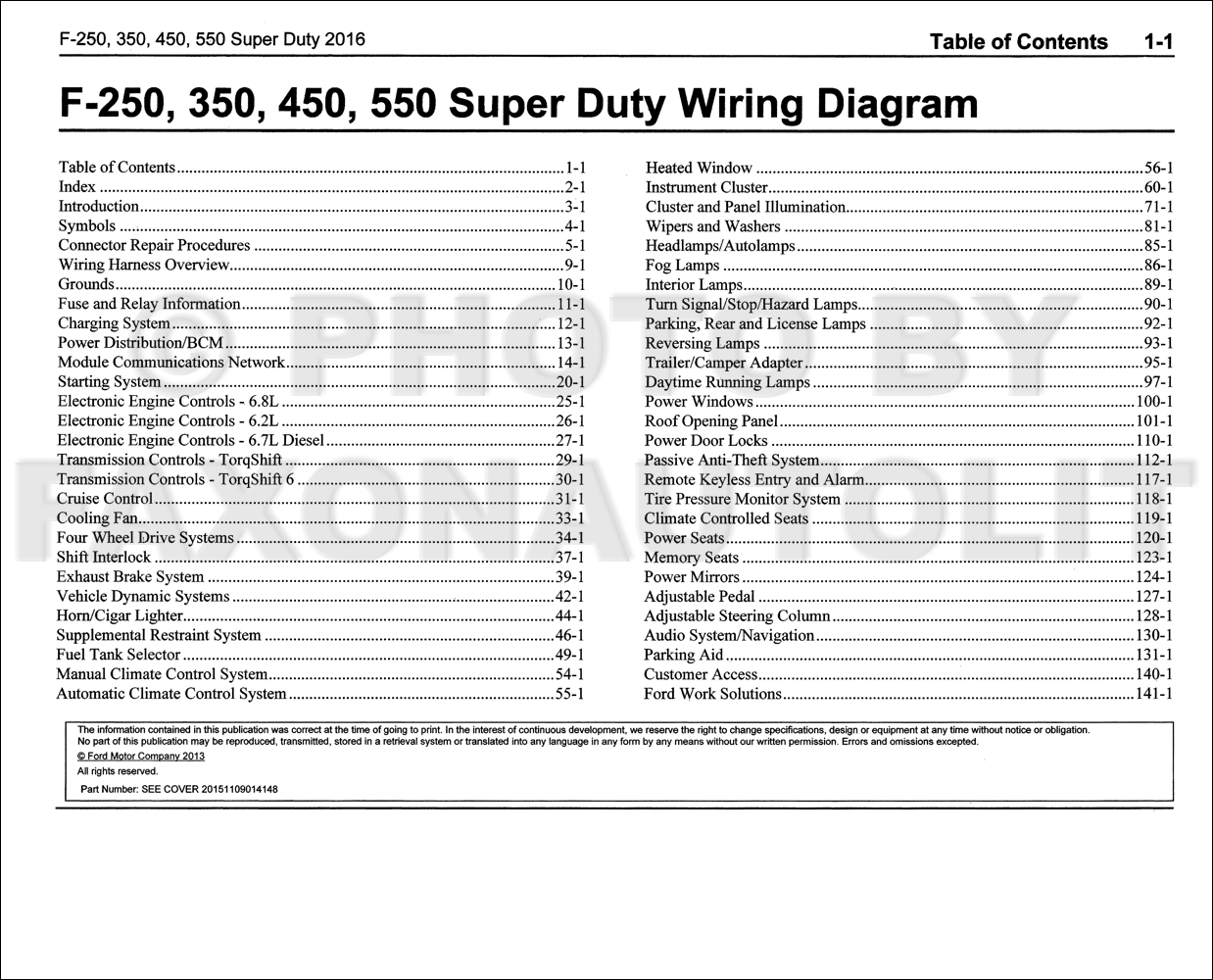
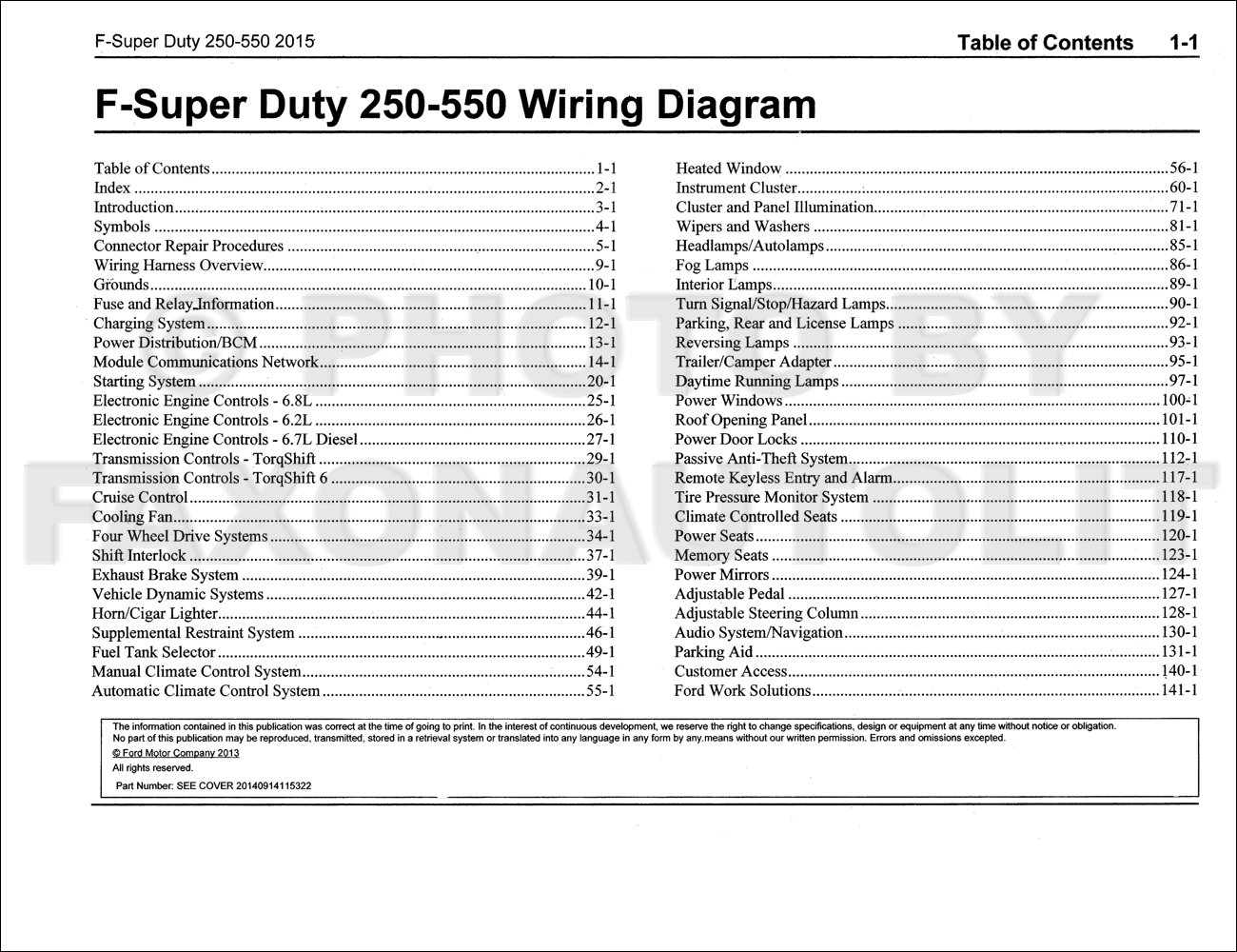
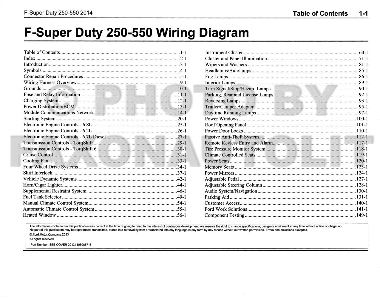
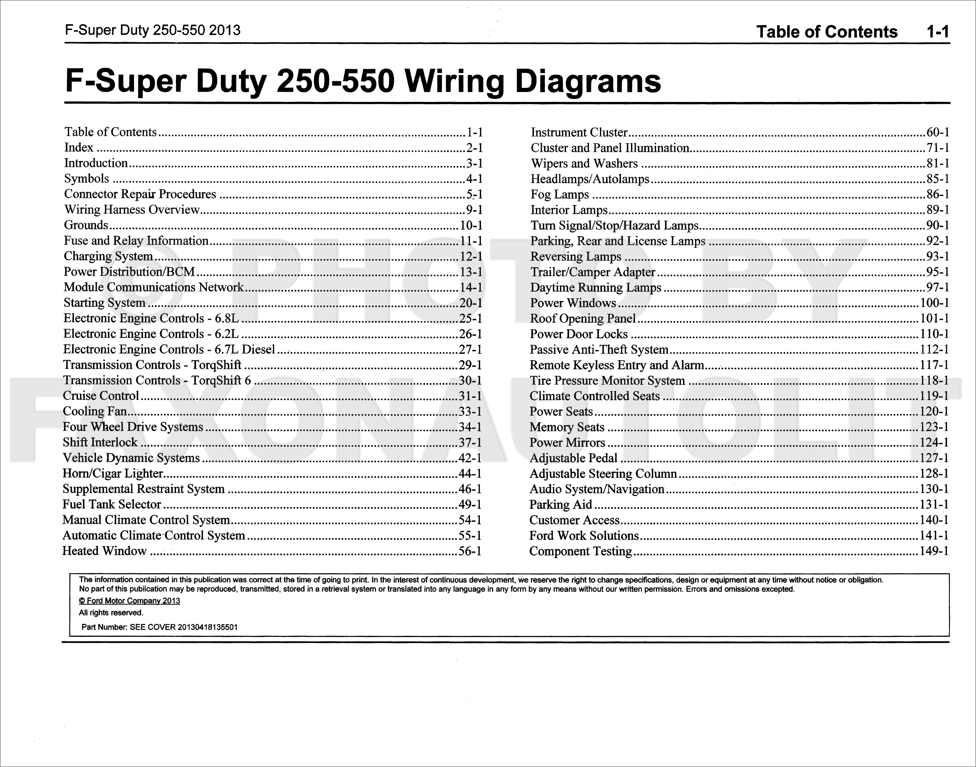
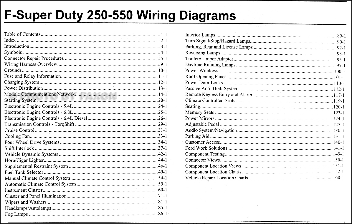
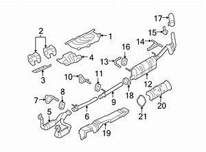 Title : Ford F 250 Super Duty Manifold Wiring Diagram
Category : Wiring Diagram
Format : PDF
Title : Ford F 250 Super Duty Manifold Wiring Diagram
Category : Wiring Diagram
Format : PDF