how-do-i-lower-the-steering-column-on-my-f350-with-tilt-wiring-diagram.pdf
1 / 83
100%
HTTP://WIRINGSCHEMA.COMRevision 2.9 (03/2022)© 2022 HTTP://WIRINGSCHEMA.COM. All Rights Reserved.
Download Full Diagram Via this App!!!!
Get Diagram Now! DOWNLOAD NOW


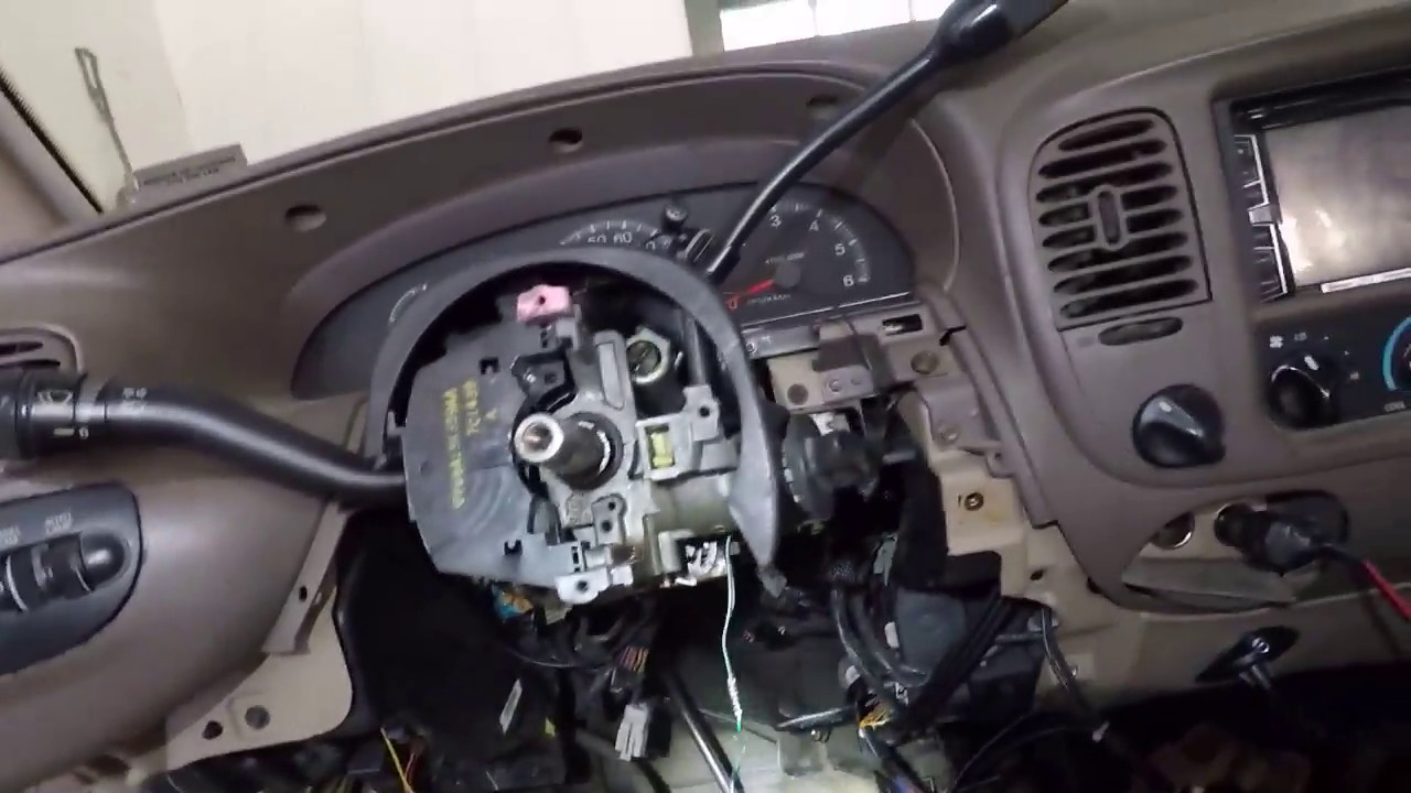
-picture197908-blinker-01-sm.jpg)
-picture197907-blinker-02-sm.jpg)