lexus-lx-470-2003-wiring-diagram.pdf
1 / 84
100%
Download Full Diagram Via this App!!!!
Get Diagram Now! DOWNLOAD NOW
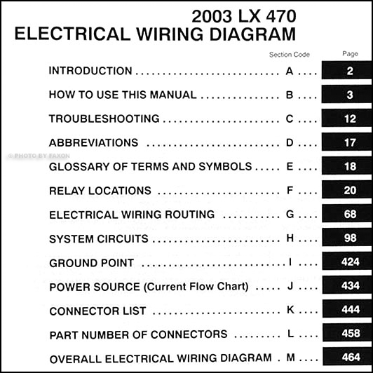
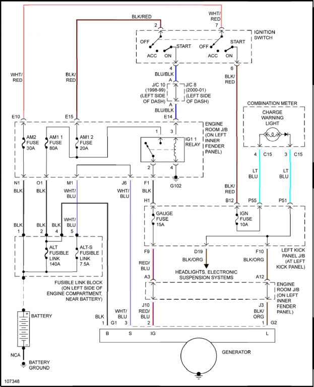
 Title : Lexus Lx 470 2003 Wiring Diagram
Category : Wiring Diagram
Format : PDF
Title : Lexus Lx 470 2003 Wiring Diagram
Category : Wiring Diagram
Format : PDF


/Page-0001.png)