lexus-lx-470-prices-reviews-and-new-model-information-wiring-diagram.pdf
1 / 92
100%
Download Full Diagram Via this App!!!!
Get Diagram Now! DOWNLOAD NOW
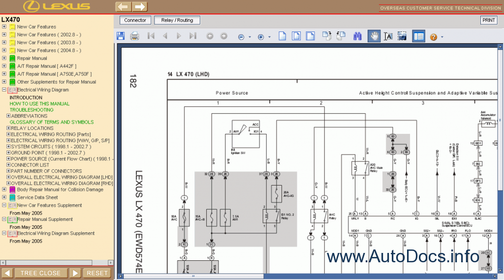
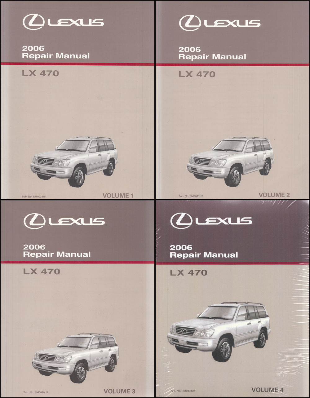
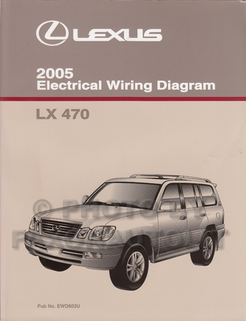
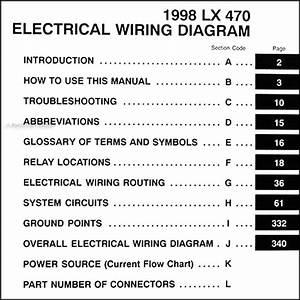 Title : Lexus Lx 470 Prices Reviews And New Model Information Wiring Diagram
Category : Wiring Diagram
Format : PDF
Title : Lexus Lx 470 Prices Reviews And New Model Information Wiring Diagram
Category : Wiring Diagram
Format : PDF