new-clark-forklift-parts-starter-pn-cl4352144-wiring-diagram.pdf
1 / 96
100%
Download Full Diagram Via this App!!!!
Get Diagram Now! DOWNLOAD NOW
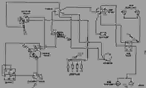
 Title : New Clark Forklift Parts Starter Pn Cl4352144 Wiring Diagram
Category : Wiring Diagram
Format : PDF
Title : New Clark Forklift Parts Starter Pn Cl4352144 Wiring Diagram
Category : Wiring Diagram
Format : PDF