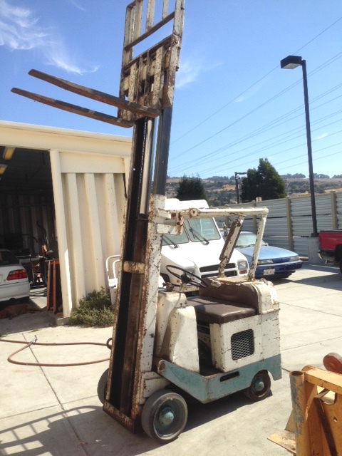
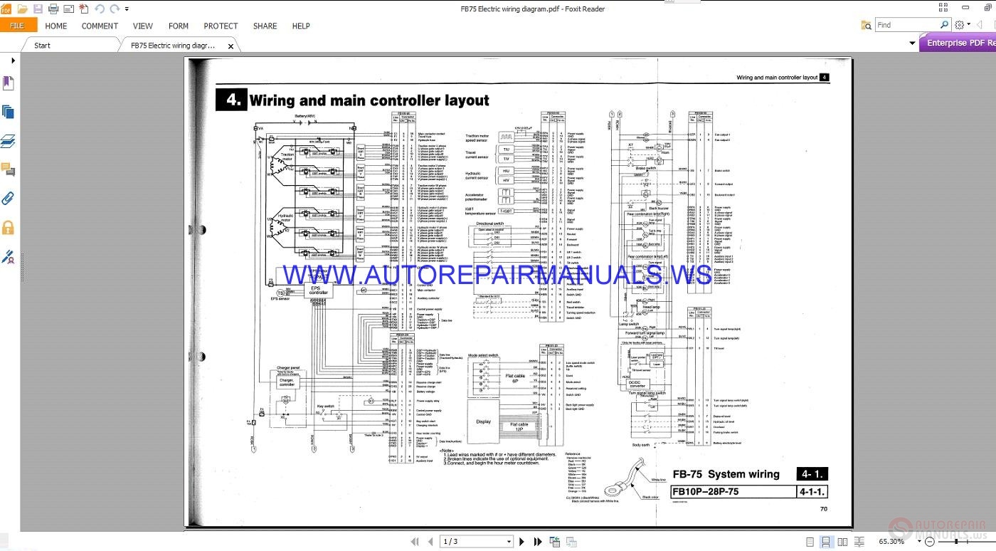
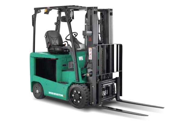
new-starter-fits-clark-mitsubishi-yale-mm115517-forklifts-wiring-diagram.pdf
100%

New Starter Fits Clark Mitsubishi Yale Mm115517 Forklifts Wiring Diagram


HTTP://WIRINGSCHEMA.COM
Revision 2.1 (02/2024)
© 2024 HTTP://WIRINGSCHEMA.COM. All Rights Reserved.

TABLE OF CONTENTS

Cover1
Table of Contents2
AIR CONDITIONING3
ANTI-LOCK BRAKES4
ANTI-THEFT5
BODY CONTROL MODULES6
COMPUTER DATA LINES7
COOLING FAN8
CRUISE CONTROL9
DEFOGGERS10
ELECTRONIC SUSPENSION11
ENGINE PERFORMANCE12
EXTERIOR LIGHTS13
GROUND DISTRIBUTION14
HEADLIGHTS15
HORN16
INSTRUMENT CLUSTER17
INTERIOR LIGHTS18
POWER DISTRIBUTION19
POWER DOOR LOCKS20
POWER MIRRORS21
POWER SEATS22
POWER WINDOWS23
RADIO24
SHIFT INTERLOCK25
STARTING/CHARGING26
SUPPLEMENTAL RESTRAINTS27
TRANSMISSION28
TRUNK, TAILGATE, FUEL DOOR29
WARNING SYSTEMS30
WIPER/WASHER31
Diagnostic Flowchart #332
Diagnostic Flowchart #433
Case Study #1 - Real-World Failure34
Case Study #2 - Real-World Failure35
Case Study #3 - Real-World Failure36
Case Study #4 - Real-World Failure37
Case Study #5 - Real-World Failure38
Case Study #6 - Real-World Failure39
Hands-On Lab #1 - Measurement Practice40
Hands-On Lab #2 - Measurement Practice41
Hands-On Lab #3 - Measurement Practice42
Hands-On Lab #4 - Measurement Practice43
Hands-On Lab #5 - Measurement Practice44
Hands-On Lab #6 - Measurement Practice45
Checklist & Form #1 - Quality Verification46
Checklist & Form #2 - Quality Verification47
Checklist & Form #3 - Quality Verification48
Checklist & Form #4 - Quality Verification49
AIR CONDITIONING Page 3

Overcurrent protection units are the overlooked champions of every wiring system. They act as silent guardians, standing between power flow and the devices that depend on it. Without them, even a small malfunctionsuch as a short circuit or overloadcould ignite serious hazards or trigger electrical fires. This guide explores their operating principles, why they are essential, and how engineers apply them in modern systems.

At the core of any protective strategy lies one simple goal: to stop the current before damage occurs. Every wire, connector, and component in a circuit is designed to handle a specific current rating. When that limit is breached, the result is thermal stresssometimes enough to melt insulation or ignite materials. Protection devices act as self-acting interrupters that disconnect power instantly to prevent failure. They are not just accessories; they are fundamental safety mechanisms that define the lifespan of every electrical installation.

Fuses are the simplest and most widely used protection elements. They contain a delicate fuse wire that melts when current exceeds a predetermined value. Once blown, the fuse must be replaced, which provides a clear visual indication that a fault has occurred. The beauty of fuses lies in their simplicity and fast reactionthey react almost instantly to overcurrent conditions. However, their one-time operation makes them more suitable for applications where faults are rare, such as automotive wiring or household devices.

In contrast, automatic breakers perform the same protective function but can be re-engaged after tripping. Inside a breaker, a thermal mechanism or solenoid trigger responds to excess current, activating a release lever that disconnects the circuit. Once the fault is cleared, the breaker can be manually switched back or automatically depending on design. This makes breakers ideal for building systems where continuous operation is essential. Breakers also come in various typesthermal, magnetic, and hybrideach tuned for specific current-time curves.

Another critical device in modern systems is the residual current device (RCD). These units monitor the balance between current flowing in the live and neutral conductors. If even a small difference is detected, indicating current leakage to ground, the device trips instantlyoften in millisecondsto stop electrocution hazards. This life-saving technology is mandatory in wet environments such as laundry areas and industrial wash areas.

Surge protectors defend circuits from transient voltage spikes caused by electromagnetic disturbances. They work by clamping excess voltage and diverting it safely to ground before it reaches sensitive equipment. Surge protective devices (SPDs) are classified by energy absorption capacity and reaction speed. When properly installed, they act as the primary barrier for electronic systems, particularly in automation panels and industrial control systems.

While each device serves a specific role, true protection comes from layering them effectively. For instance, a main electrical board might use fuses for branch circuits and SPDs for surge suppression. This layered defense ensures that no single fault can propagate through the entire network. Engineers refer to this as selective coordination, where each device acts in sequence, isolating only the faulty part of the circuit.

Maintenance and inspection play equally vital roles. Over time, circuit protectors can wear outfuse clips corrode, coils weaken, and surge modules deteriorate after repeated surges. Regular testing with megohm testers and thermal imaging cameras helps detect weak points before they cause downtime. Professionals also document tripping history, as repeated faults often indicate underlying design or grounding issues rather than random failures.

In advanced installations, protection is no longer purely mechanical. Electronic circuit protection uses semiconductor-based switches to monitor and limit current dynamically. These smart fuses can respond within microseconds and provide real-time feedback through digital networks, allowing predictive maintenance and early failure detection. They are increasingly used in robotics, where efficiency and reliability are mandatory.

Ultimately, mastering protective design means understanding responsibility. Every protective component is a safeguard for machinery and human life. When selected, installed, and maintained properly, they embody the principle that safety defines good design, not convenience.

Figure 1
ANTI-LOCK BRAKES Page 4

Electrical safety begins with self-discipline. Cut and lock power first, before you put a hand on a live path. Be aware of stored-energy parts such as backup supplies and large capacitors. Keep tools in good condition and replace damaged insulation immediately.

Handling live or delicate components requires patience. Do not yank a connector by the wires; use its release tab. Maintain proper cable strain relief and avoid over-tightening clamps. Route data lines away from heavy load wires to prevent induced noise. Use approved contact cleaner rather than sanding or scraping pins.

After completing work, test voltage levels and insulation resistance. Make sure guards are back in place and labels can still be read clearly. Conduct a visual inspection one last time before applying power. Real safety is the sum of many careful habits, not one dramatic step.

Figure 2
ANTI-THEFT Page 5

A single sheet often shows power rails, data links, and control authority all together. Bold lines are typically high current, thin lines are signal/data, and dashed outlines indicate shields or grouped harnesses. Those visual cues help you tell heavy-load feeds from delicate signal lines in “New Starter Fits Clark Mitsubishi Yale Mm115517 Forklifts Wiring Diagram”.

The short codes on those paths finish the story. Tags like CAN-H, CAN-L, LIN BUS, SCL, SDA, TX, RX identify comms; B+, 12V SW, 5V REF, GND CHASSIS identify power / reference. If you confuse those, you may shove voltage down a data pin and instantly cook a controller in Wiring Diagram.

So in 2026, always confirm: is this a data path or a power feed before you energize anything on “New Starter Fits Clark Mitsubishi Yale Mm115517 Forklifts Wiring Diagram”. Checking that first protects sensitive hardware and protects http://wiringschema.com from unnecessary liability. Record probe locations and attach them to https://http://wiringschema.com/new-starter-fits-clark-mitsubishi-yale-mm115517-forklifts-wiring-diagram/ so there’s a service trail for whoever works on it next.

Figure 3
BODY CONTROL MODULES Page 6

Understanding wire colors and sizes is fundamental for creating reliable and safe electrical systems.
Wire color identifies the circuit’s function, and its gauge defines both current rating and resistance value.
Recognizing the role of color and size minimizes heat buildup, shorts, and unwanted voltage variation.
For example, red wires are generally used for positive voltage, black or brown for ground, yellow for ignition or control, and blue for communication lines.
By maintaining proper color coding and gauge selection, technicians ensure both clarity and safety during inspection, maintenance, and installation in “New Starter Fits Clark Mitsubishi Yale Mm115517 Forklifts Wiring Diagram”.

In Wiring Diagram, electrical engineers and technicians follow internationally recognized standards like ISO 6722, SAE J1128, and IEC 60228 to achieve consistent wire identification.
They include detailed data on conductor composition, cross-section, and heat resistance for each category.
For example, 1.5 mm² wiring fits low-current sensors, whereas 4–6 mm² wires feed high-power or heating circuits.
Understanding how to match wire size to current and voltage requirements is essential to avoid electrical faults and system degradation.
When designing or repairing “New Starter Fits Clark Mitsubishi Yale Mm115517 Forklifts Wiring Diagram”, engineers must check both the electrical rating and insulation properties before installation.

Accurate documentation is one of the cornerstones of proper wiring practice.
All wire replacements or adjustments should be written into the maintenance report for future traceability.
Proper documentation makes future troubleshooting and upgrades faster by removing guesswork.
Engineers should upload the latest diagrams, measurement logs, and photos of wiring updates to http://wiringschema.com.
Listing the completion year (2026) and attaching https://http://wiringschema.com/new-starter-fits-clark-mitsubishi-yale-mm115517-forklifts-wiring-diagram/ as reference helps track all safety-compliant work.
Meticulous record-keeping is both a technical standard and a professional ethic that protects system reliability.

Figure 4
COMPUTER DATA LINES Page 7

Power distribution is the organized method of channeling electricity from a main supply into multiple controlled circuits.
It maintains consistent power delivery so that all parts of “New Starter Fits Clark Mitsubishi Yale Mm115517 Forklifts Wiring Diagram” operate with the right voltage and amperage.
Without a proper distribution network, systems could face power losses, overheating, or electrical instability that leads to failure.
An optimized design keeps voltage steady, protects sensitive devices, and minimizes the risk of overload or short circuits.
Hence, power distribution serves as the core framework enabling stable and secure system performance.

Building a high-quality power distribution system requires careful planning and adherence to engineering standards.
Cables, fuses, and relays must be selected according to electrical capacity, environment, and operation cycle.
Engineers in Wiring Diagram typically follow ISO 16750, IEC 61000, and SAE J1113 to ensure consistent safety and performance.
Separate high-current cables from data and control lines to reduce electromagnetic noise.
Fuse boxes and relay modules must be arranged for quick access and clearly identified for service.
Such careful planning ensures “New Starter Fits Clark Mitsubishi Yale Mm115517 Forklifts Wiring Diagram” remains energy-efficient and dependable everywhere.

Following installation, verification ensures that all power circuits comply with technical standards.
Electrical inspectors should check resistance, verify voltage stability, and test all protective components.
Any cable reroute or update must be recorded in drawings and saved in maintenance archives.
All test results and supporting files must be archived in http://wiringschema.com for reference and review.
Attaching 2026 and https://http://wiringschema.com/new-starter-fits-clark-mitsubishi-yale-mm115517-forklifts-wiring-diagram/ provides transparent maintenance history for future checks.
Proper testing and recordkeeping help “New Starter Fits Clark Mitsubishi Yale Mm115517 Forklifts Wiring Diagram” stay durable, efficient, and regulation-compliant.

Figure 5
COOLING FAN Page 8

It serves as a key protective feature allowing safe energy flow under both normal and abnormal conditions.
It acts as the bridge between electrical installations and the earth, stabilizing voltage levels and reducing the risk of electric shock.
If grounding is missing, “New Starter Fits Clark Mitsubishi Yale Mm115517 Forklifts Wiring Diagram” may experience voltage surges, EMI, and potential safety hazards.
Proper grounding provides a controlled path for fault currents to dissipate safely, preventing system failure or fire.
Across Wiring Diagram, grounding is considered the backbone of sustainable electrical system performance.

Grounding design first requires a study of the environment and the earth’s resistance characteristics.
All grounding joints should be mechanically firm, rust-proof, and maintain low resistance for years.
Across Wiring Diagram, grounding practices comply with IEC 60364 and IEEE 142 to align with global safety standards.
Engineers must ensure that grounding conductors are appropriately sized and all metallic parts are bonded together.
A single potential plane across the system avoids dangerous voltage gradients and improves system safety.
By following these principles, “New Starter Fits Clark Mitsubishi Yale Mm115517 Forklifts Wiring Diagram” maintains optimal stability, reduced interference, and improved electrical performance.

Regular testing and analysis keep grounding systems effective and compliant with safety standards.
Technicians must check ground resistance, inspect connectors, and record performance data.
If corrosion or loose fittings are found, immediate maintenance and retesting should be performed.
Detailed maintenance logs and inspection results must be preserved for auditing and compliance.
Regular testing each 2026 confirms that grounding continues to meet safety requirements.
By following maintenance schedules, “New Starter Fits Clark Mitsubishi Yale Mm115517 Forklifts Wiring Diagram” ensures continued safety, reliability, and performance.

Figure 6
CRUISE CONTROL Page 9

New Starter Fits Clark Mitsubishi Yale Mm115517 Forklifts Wiring Diagram – Connector Index & Pinout Guide 2026

Routine connector cleaning greatly improves long-term system reliability. {Dirt, oil, and oxidation can build up on terminals, increasing resistance and causing voltage drops.|Contamination inside connectors often leads to intermittent faults and sensor malfunctions.|A layer of corrosion or grime can disrupt even...

Technicians should use electrical contact cleaner sprays designed specifically for connectors. {For stubborn oxidation, a soft brush or lint-free swab can be used carefully on exposed metal surfaces.|Gently brushing corroded pins restores conductivity while maintaining plating integrity.|Never use abrasive materials that could scratch or ...

After cleaning, allow connectors to dry completely before reassembly. Consistent cleaning practices extend harness life and improve diagnostic accuracy.

Figure 7
DEFOGGERS Page 10

New Starter Fits Clark Mitsubishi Yale Mm115517 Forklifts Wiring Diagram Full Manual – Sensor Inputs Reference 2026

Temperature input circuits provide essential data for engine, HVAC, and battery management systems. {Common types include thermistors, thermocouples, and resistance temperature detectors (RTDs).|Different applications use specific temperature sensors such as NTC, PTC, or infrared-based types....

Thermistors change their resistance depending on the surrounding temperature. {Thermocouples, on the other hand, generate a small voltage based on the temperature difference between two dissimilar metals.|These are commonly used in exhaust systems or industrial heating equipment.|RTDs provide precise and ...

Always measure resistance under the specified temperature conditions for accurate diagnosis. {Proper understanding of temperature sensors ensures stable thermal control and system efficiency.|Mastering temperature input circuits improves diagnostic accuracy and reliability.|Correct handling of thermal sens...

Figure 8
ELECTRONIC SUSPENSION Page 11

New Starter Fits Clark Mitsubishi Yale Mm115517 Forklifts Wiring Diagram Wiring Guide – Actuator Outputs 2026

Stepper motors are precision actuators that rotate in small, controlled increments. {Each step corresponds to a specific angular displacement determined by motor design.|The ECU or controller sends sequential pulse signals to drive the motor coil phases.|By controlling pulse timing and order, the motor achieves accurate pos...

Bipolar stepper motors provide higher torque and efficiency but require H-bridge control. In automotive systems, they are often used for idle air control or gauge actuation.

PWM signals regulate torque and speed while minimizing vibration. Technicians should verify stepper operation using an oscilloscope to inspect pulse patterns.

Figure 9
ENGINE PERFORMANCE Page 12

New Starter Fits Clark Mitsubishi Yale Mm115517 Forklifts Wiring Diagram Full Manual – Sensor Inputs Reference 2026

Pressure sensors measure fluid or air pressure and convert it into an electrical signal for monitoring systems. {They help maintain safety and efficiency by reporting pressure variations to the control unit.|Monitoring pressure ensures balanced operation in engines, brakes, and HVAC circuits.|Accurate pressure data allow...

Capacitive sensors detect distance change between plates as pressure alters the capacitance. {The signal is processed by the ECU to adjust system response such as fuel injection, boost control, or safety cutoff.|Electrical output is scaled to reflect actual mechanical pressure values.|The controller interprets voltage ...

Technicians should always compare measured output with manufacturer specifications using a multimeter or scan tool. {Proper maintenance of pressure sensors ensures reliable system feedback and longer component lifespan.|Consistent calibration prevents false alerts or control instability.|Understanding pressure sensor inputs helps improve s...

Figure 10
EXTERIOR LIGHTS Page 13

As the distributed nervous system of the
vehicle, the communication bus eliminates bulky point-to-point wiring by
delivering unified message pathways that significantly reduce harness
mass and electrical noise. By enforcing timing discipline and
arbitration rules, the system ensures each module receives critical
updates without interruption.

Modern platforms rely on a hierarchy of standards including CAN for
deterministic control, LIN for auxiliary functions, FlexRay for
high-stability timing loops, and Ethernet for high-bandwidth sensing.
Each protocol fulfills unique performance roles that enable safe
coordination of braking, torque management, climate control, and
driver-assistance features.

Communication failures may arise from impedance drift, connector
oxidation, EMI bursts, or degraded shielding, often manifesting as
intermittent sensor dropouts, delayed actuator behavior, or corrupted
frames. Diagnostics require voltage verification, termination checks,
and waveform analysis to isolate the failing segment.

Figure 11
GROUND DISTRIBUTION Page 14

Protection systems in New Starter Fits Clark Mitsubishi Yale Mm115517 Forklifts Wiring Diagram 2026 Wiring Diagram rely on fuses and relays
to form a controlled barrier between electrical loads and the vehicle’s
power distribution backbone. These elements react instantly to abnormal
current patterns, stopping excessive amperage before it cascades into
critical modules. By segmenting circuits into isolated branches, the
system protects sensors, control units, lighting, and auxiliary
equipment from thermal stress and wiring burnout.

Automotive fuses vary from micro types to high‑capacity cartridge
formats, each tailored to specific amperage tolerances and activation
speeds. Relays complement them by acting as electronically controlled
switches that manage high‑current operations such as cooling fans, fuel
systems, HVAC blowers, window motors, and ignition‑related loads. The
synergy between rapid fuse interruption and precision relay switching
establishes a controlled electrical environment across all driving
conditions.

Technicians often
diagnose issues by tracking inconsistent current delivery, noisy relay
actuation, unusual voltage fluctuations, or thermal discoloration on
fuse panels. Addressing these problems involves cleaning terminals,
reseating connectors, conditioning ground paths, and confirming load
consumption through controlled testing. Maintaining relay responsiveness
and fuse integrity ensures long‑term electrical stability.

Figure 12
HEADLIGHTS Page 15

Within modern automotive systems, reference
pads act as structured anchor locations for resistance-profile
comparison, enabling repeatable and consistent measurement sessions.
Their placement across sensor returns, control-module feeds, and
distribution junctions ensures that technicians can evaluate baseline
conditions without interference from adjacent circuits. This allows
diagnostic tools to interpret subsystem health with greater accuracy.

Using their strategic layout, test points enable
resistance-profile comparison, ensuring that faults related to thermal
drift, intermittent grounding, connector looseness, or voltage
instability are detected with precision. These checkpoints streamline
the troubleshooting workflow by eliminating unnecessary inspection of
unrelated harness branches and focusing attention on the segments most
likely to generate anomalies.

Frequent discoveries made at reference nodes
involve irregular waveform signatures, contact oxidation, fluctuating
supply levels, and mechanical fatigue around connector bodies.
Diagnostic procedures include load simulation, voltage-drop mapping, and
ground potential verification to ensure that each subsystem receives
stable and predictable electrical behavior under all operating
conditions.

Figure 13
HORN Page 16

In modern systems,
structured diagnostics rely heavily on reference-signal stabilization
analysis, allowing technicians to capture consistent reference data
while minimizing interference from adjacent circuits. This structured
approach improves accuracy when identifying early deviations or subtle
electrical irregularities within distributed subsystems.

Field evaluations often
incorporate reference-signal stabilization analysis, ensuring
comprehensive monitoring of voltage levels, signal shape, and
communication timing. These measurements reveal hidden failures such as
intermittent drops, loose contacts, or EMI-driven distortions.

Common measurement findings include fluctuating supply rails, irregular
ground returns, unstable sensor signals, and waveform distortion caused
by EMI contamination. Technicians use oscilloscopes, multimeters, and
load probes to isolate these anomalies with precision.

Figure 14
INSTRUMENT CLUSTER Page 17

Troubleshooting for New Starter Fits Clark Mitsubishi Yale Mm115517 Forklifts Wiring Diagram 2026 Wiring Diagram begins with primary
verification cycle, ensuring the diagnostic process starts with clarity
and consistency. By checking basic system readiness, technicians avoid
deeper misinterpretations.

Technicians use latency and delay tracking to narrow fault origins. By
validating electrical integrity and observing behavior under controlled
load, they identify abnormal deviations early.

Branches exposed to road vibration often develop micro‑cracks in
conductors. Flex tests combined with continuity monitoring help identify
weak segments.

Figure 15
INTERIOR LIGHTS Page 18

Across diverse vehicle architectures, issues related to
subsystem drift from long-term thermal-cycling fatigue represent a
dominant source of unpredictable faults. These faults may develop
gradually over months of thermal cycling, vibrations, or load
variations, ultimately causing operational anomalies that mimic
unrelated failures. Effective troubleshooting requires technicians to
start with a holistic overview of subsystem behavior, forming accurate
expectations about what healthy signals should look like before
proceeding.

When examining faults tied to subsystem drift from long-term
thermal-cycling fatigue, technicians often observe fluctuations that
correlate with engine heat, module activation cycles, or environmental
humidity. These conditions can cause reference rails to drift or sensor
outputs to lose linearity, leading to miscommunication between control
units. A structured diagnostic workflow involves comparing real-time
readings to known-good values, replicating environmental conditions, and
isolating behavior changes under controlled load simulations.

Persistent problems associated with subsystem drift from long-term
thermal-cycling fatigue can escalate into module desynchronization,
sporadic sensor lockups, or complete loss of communication on shared
data lines. Technicians must examine wiring paths for mechanical
fatigue, verify grounding architecture stability, assess connector
tension, and confirm that supply rails remain steady across temperature
changes. Failure to address these foundational issues often leads to
repeated return visits.

Figure 16
POWER DISTRIBUTION Page 19

For
long-term system stability, effective electrical upkeep prioritizes
continuity-path reliability improvement, allowing technicians to
maintain predictable performance across voltage-sensitive components.
Regular inspections of wiring runs, connector housings, and grounding
anchors help reveal early indicators of degradation before they escalate
into system-wide inconsistencies.

Technicians
analyzing continuity-path reliability improvement typically monitor
connector alignment, evaluate oxidation levels, and inspect wiring for
subtle deformations caused by prolonged thermal exposure. Protective
dielectric compounds and proper routing practices further contribute to
stable electrical pathways that resist mechanical stress and
environmental impact.

Issues associated with continuity-path reliability improvement
frequently arise from overlooked early wear signs, such as minor contact
resistance increases or softening of insulation under prolonged heat.
Regular maintenance cycles—including resistance indexing, pressure
testing, and moisture-barrier reinforcement—ensure that electrical
pathways remain dependable and free from hidden vulnerabilities.

Figure 17
POWER DOOR LOCKS Page 20

In
many vehicle platforms, the appendix operates as a universal alignment
guide centered on connector family classification and labeling
consistency, helping technicians maintain consistency when analyzing
circuit diagrams or performing diagnostic routines. This reference
section prevents confusion caused by overlapping naming systems or
inconsistent labeling between subsystems, thereby establishing a unified
technical language.

Material within the appendix covering connector
family classification and labeling consistency often features
quick‑access charts, terminology groupings, and definition blocks that
serve as anchors during diagnostic work. Technicians rely on these
consolidated references to differentiate between similar connector
profiles, categorize branch circuits, and verify signal
classifications.

Comprehensive references for connector family classification and
labeling consistency also support long‑term documentation quality by
ensuring uniform terminology across service manuals, schematics, and
diagnostic tools. When updates occur—whether due to new sensors, revised
standards, or subsystem redesigns—the appendix remains the authoritative
source for maintaining alignment between engineering documentation and
real‑world service practices.

Figure 18
POWER MIRRORS Page 21

Deep analysis of signal integrity in New Starter Fits Clark Mitsubishi Yale Mm115517 Forklifts Wiring Diagram 2026 Wiring Diagram requires
investigating how differential-mode noise in sensor feedback circuits
disrupts expected waveform performance across interconnected circuits.
As signals propagate through long harnesses, subtle distortions
accumulate due to impedance shifts, parasitic capacitance, and external
electromagnetic stress. This foundational assessment enables technicians
to understand where integrity loss begins and how it
evolves.

Patterns associated with differential-mode noise in
sensor feedback circuits often appear during subsystem
switching—ignition cycles, relay activation, or sudden load
redistribution. These events inject disturbances through shared
conductors, altering reference stability and producing subtle waveform
irregularities. Multi‑state capture sequences are essential for
distinguishing true EMC faults from benign system noise.

Left uncorrected, differential-mode noise in sensor feedback circuits
can progress into widespread communication degradation, module
desynchronization, or unstable sensor logic. Technicians must verify
shielding continuity, examine grounding symmetry, analyze differential
paths, and validate signal behavior across environmental extremes. Such
comprehensive evaluation ensures repairs address root EMC
vulnerabilities rather than surface‑level symptoms.

Figure 19
POWER SEATS Page 22

Deep technical assessment of EMC interactions must account for
over‑termination and its impact on high‑speed buses, as the resulting
disturbances can propagate across wiring networks and disrupt
timing‑critical communication. These disruptions often appear
sporadically, making early waveform sampling essential to characterize
the extent of electromagnetic influence across multiple operational
states.

Systems experiencing over‑termination and its
impact on high‑speed buses frequently show inconsistencies during fast
state transitions such as ignition sequencing, data bus arbitration, or
actuator modulation. These inconsistencies originate from embedded EMC
interactions that vary with harness geometry, grounding quality, and
cable impedance. Multi‑stage capture techniques help isolate the root
interaction layer.

Long-term exposure to over‑termination and its impact on high‑speed
buses can lead to accumulated timing drift, intermittent arbitration
failures, or persistent signal misalignment. Corrective action requires
reinforcing shielding structures, auditing ground continuity, optimizing
harness layout, and balancing impedance across vulnerable lines. These
measures restore waveform integrity and mitigate progressive EMC
deterioration.

Figure 20
POWER WINDOWS Page 23

Deep diagnostic exploration of signal integrity in New Starter Fits Clark Mitsubishi Yale Mm115517 Forklifts Wiring Diagram 2026
Wiring Diagram must consider how vibration-induced microgaps creating
intermittent EMC hotspots alters the electrical behavior of
communication pathways. As signal frequencies increase or environmental
electromagnetic conditions intensify, waveform precision becomes
sensitive to even minor impedance gradients. Technicians therefore begin
evaluation by mapping signal propagation under controlled conditions and
identifying baseline distortion characteristics.

When vibration-induced microgaps creating intermittent EMC hotspots is
active within a vehicle’s electrical environment, technicians may
observe shift in waveform symmetry, rising-edge deformation, or delays
in digital line arbitration. These behaviors require examination under
multiple load states, including ignition operation, actuator cycling,
and high-frequency interference conditions. High-bandwidth oscilloscopes
and calibrated field probes reveal the hidden nature of such
distortions.

If
unchecked, vibration-induced microgaps creating intermittent EMC
hotspots can escalate into broader electrical instability, causing
corruption of data frames, synchronization loss between modules, and
unpredictable actuator behavior. Effective corrective action requires
ground isolation improvements, controlled harness rerouting, adaptive
termination practices, and installation of noise-suppression elements
tailored to the affected frequency range.

Figure 21
RADIO Page 24

Evaluating advanced signal‑integrity interactions involves
examining the influence of reflected‑energy accumulation from partial
harness terminations, a phenomenon capable of inducing significant
waveform displacement. These disruptions often develop gradually,
becoming noticeable only when communication reliability begins to drift
or subsystem timing loses coherence.

When reflected‑energy accumulation from partial harness terminations is
active, waveform distortion may manifest through amplitude instability,
reference drift, unexpected ringing artifacts, or shifting propagation
delays. These effects often correlate with subsystem transitions,
thermal cycles, actuator bursts, or environmental EMI fluctuations.
High‑bandwidth test equipment reveals the microscopic deviations hidden
within normal signal envelopes.

Long‑term exposure to reflected‑energy accumulation from partial
harness terminations can create cascading waveform degradation,
arbitration failures, module desynchronization, or persistent sensor
inconsistency. Corrective strategies include impedance tuning, shielding
reinforcement, ground‑path rebalancing, and reconfiguration of sensitive
routing segments. These adjustments restore predictable system behavior
under varied EMI conditions.

Figure 22
SHIFT INTERLOCK Page 25

In-depth
signal integrity analysis requires understanding how harmonic stacking
during injector modulation cycles influences propagation across
mixed-frequency network paths. These distortions may remain hidden
during low-load conditions, only becoming evident when multiple modules
operate simultaneously or when thermal boundaries shift.

Systems exposed to harmonic stacking during injector
modulation cycles often show instability during rapid subsystem
transitions. This instability results from interference coupling into
sensitive wiring paths, causing skew, jitter, or frame corruption.
Multi-domain waveform capture reveals how these disturbances propagate
and interact.

Long-term exposure to harmonic stacking during injector modulation
cycles can lead to cumulative communication degradation, sporadic module
resets, arbitration errors, and inconsistent sensor behavior.
Technicians mitigate these issues through grounding rebalancing,
shielding reinforcement, optimized routing, precision termination, and
strategic filtering tailored to affected frequency bands.

Figure 23
STARTING/CHARGING Page 26

This section on STARTING/CHARGING explains how these principles apply to starter fits clark mitsubishi yale mm115517 forklifts wiring diagram systems. Focus on repeatable tests, clear documentation, and safe handling. Keep a simple log: symptom → test → reading → decision → fix.

Figure 24
SUPPLEMENTAL RESTRAINTS Page 27

The engineering process behind
Harness Layout Variant #2 evaluates how heat-shield integration for
cables near thermal hotspots interacts with subsystem density, mounting
geometry, EMI exposure, and serviceability. This foundational planning
ensures clean routing paths and consistent system behavior over the
vehicle’s full operating life.

During refinement, heat-shield integration for cables near thermal
hotspots impacts EMI susceptibility, heat distribution, vibration
loading, and ground continuity. Designers analyze spacing, elevation
changes, shielding alignment, tie-point positioning, and path curvature
to ensure the harness resists mechanical fatigue while maintaining
electrical integrity.

Managing heat-shield integration for cables near thermal hotspots
effectively results in improved robustness, simplified maintenance, and
enhanced overall system stability. Engineers apply isolation rules,
structural reinforcement, and optimized routing logic to produce a
layout capable of sustaining long-term operational loads.

Figure 25
TRANSMISSION Page 28

Engineering Harness Layout
Variant #3 involves assessing how deformation‑tolerant harness sections
for flexible body panels influences subsystem spacing, EMI exposure,
mounting geometry, and overall routing efficiency. As harness density
increases, thoughtful initial planning becomes critical to prevent
premature system fatigue.

During refinement, deformation‑tolerant harness sections for flexible
body panels can impact vibration resistance, shielding effectiveness,
ground continuity, and stress distribution along key segments. Designers
analyze bundle thickness, elevation shifts, structural transitions, and
separation from high‑interference components to optimize both mechanical
and electrical performance.

If not addressed,
deformation‑tolerant harness sections for flexible body panels may lead
to premature insulation wear, abrasion hotspots, intermittent electrical
noise, or connector fatigue. Balanced tensioning, routing symmetry, and
strategic material selection significantly mitigate these risks across
all major vehicle subsystems.

Figure 26
TRUNK, TAILGATE, FUEL DOOR Page 29

Harness Layout Variant #4 for New Starter Fits Clark Mitsubishi Yale Mm115517 Forklifts Wiring Diagram 2026 Wiring Diagram emphasizes heat-shield standoff geometry near turbo
and exhaust paths, combining mechanical and electrical considerations to maintain cable stability across
multiple vehicle zones. Early planning defines routing elevation, clearance from heat sources, and anchoring
points so each branch can absorb vibration and thermal expansion without overstressing connectors.

During refinement, heat-shield standoff geometry near turbo and exhaust paths influences grommet
placement, tie-point spacing, and bend-radius decisions. These parameters determine whether the harness can
endure heat cycles, structural motion, and chassis vibration. Power–data separation rules, ground-return
alignment, and shielding-zone allocation help suppress interference without hindering manufacturability.

Proper control of heat-shield standoff geometry near
turbo and exhaust paths minimizes moisture intrusion, terminal corrosion, and cross-path noise. Best practices
include labeled manufacturing references, measured service loops, and HV/LV clearance audits. When components
are updated, route documentation and measurement points simplify verification without dismantling the entire
assembly.

Figure 27
WARNING SYSTEMS Page 30

The initial stage of
Diagnostic Flowchart #1 emphasizes tiered diagnostic branching for complex multi‑module faults, ensuring that
the most foundational electrical references are validated before branching into deeper subsystem evaluation.
This reduces misdirection caused by surface‑level symptoms. Mid‑stage analysis integrates tiered diagnostic
branching for complex multi‑module faults into a structured decision tree, allowing each measurement to
eliminate specific classes of faults. By progressively narrowing the fault domain, the technician accelerates
isolation of underlying issues such as inconsistent module timing, weak grounds, or intermittent sensor
behavior. A complete
validation cycle ensures tiered diagnostic branching for complex multi‑module faults is confirmed across all
operational states. Documenting each decision point creates traceability, enabling faster future diagnostics
and reducing the chance of repeat failures.

Figure 28
WIPER/WASHER Page 31

The initial phase of Diagnostic Flowchart #2
emphasizes progressive mapping of sensor-to-ECU latency anomalies, ensuring that technicians validate
foundational electrical relationships before evaluating deeper subsystem interactions. This prevents
diagnostic drift and reduces unnecessary component replacements. Throughout the flowchart, progressive mapping of sensor-to-ECU latency anomalies interacts with
verification procedures involving reference stability, module synchronization, and relay or fuse behavior.
Each decision point eliminates entire categories of possible failures, allowing the technician to converge
toward root cause faster. If
progressive mapping of sensor-to-ECU latency anomalies is not thoroughly examined, intermittent signal
distortion or cascading electrical faults may remain hidden. Reinforcing each decision node with precise
measurement steps prevents misdiagnosis and strengthens long-term reliability.

Figure 29
Diagnostic Flowchart #3 Page 32

Diagnostic Flowchart #3 for New Starter Fits Clark Mitsubishi Yale Mm115517 Forklifts Wiring Diagram 2026 Wiring Diagram initiates with fuse and relay behavior mapping under
temperature load, establishing a strategic entry point for technicians to separate primary electrical faults
from secondary symptoms. By evaluating the system from a structured baseline, the diagnostic process becomes
far more efficient. As the flowchart
progresses, fuse and relay behavior mapping under temperature load defines how mid‑stage decisions are
segmented. Technicians sequentially eliminate power, ground, communication, and actuation domains while
interpreting timing shifts, signal drift, or misalignment across related circuits. If fuse and
relay behavior mapping under temperature load is not thoroughly verified, hidden electrical inconsistencies
may trigger cascading subsystem faults. A reinforced decision‑tree process ensures all potential contributors
are validated.

Figure 30
Diagnostic Flowchart #4 Page 33

Diagnostic Flowchart #4 for New Starter Fits Clark Mitsubishi Yale Mm115517 Forklifts Wiring Diagram 2026 Wiring Diagram focuses on deep‑state verification of post‑fault ECU
synchronization, laying the foundation for a structured fault‑isolation path that eliminates guesswork and
reduces unnecessary component swapping. The first stage examines core references, voltage stability, and
baseline communication health to determine whether the issue originates in the primary network layer or in a
secondary subsystem. Technicians follow a branched decision flow that evaluates signal symmetry, grounding
patterns, and frame stability before advancing into deeper diagnostic layers. As the evaluation continues, deep‑state verification of post‑fault ECU
synchronization becomes the controlling factor for mid‑level branch decisions. This includes correlating
waveform alignment, identifying momentary desync signatures, and interpreting module wake‑timing conflicts. By
dividing the diagnostic pathway into focused electrical domains—power delivery, grounding integrity,
communication architecture, and actuator response—the flowchart ensures that each stage removes entire
categories of faults with minimal overlap. This structured segmentation accelerates troubleshooting and
increases diagnostic precision. The final stage ensures that deep‑state verification of post‑fault ECU synchronization is
validated under multiple operating conditions, including thermal stress, load spikes, vibration, and state
transitions. These controlled stress points help reveal hidden instabilities that may not appear during static
testing. Completing all verification nodes ensures long‑term stability, reducing the likelihood of recurring
issues and enabling technicians to document clear, repeatable steps for future diagnostics.

Figure 31
Case Study #1 - Real-World Failure Page 34

Case Study #1 for New Starter Fits Clark Mitsubishi Yale Mm115517 Forklifts Wiring Diagram 2026 Wiring Diagram examines a real‑world failure involving transmission‑module
torque‑signal corruption due to EMI bursts. The issue first appeared as an intermittent symptom that did not
trigger a consistent fault code, causing technicians to suspect unrelated components. Early observations
highlighted irregular electrical behavior, such as momentary signal distortion, delayed module responses, or
fluctuating reference values. These symptoms tended to surface under specific thermal, vibration, or load
conditions, making replication difficult during static diagnostic tests. Further investigation into
transmission‑module torque‑signal corruption due to EMI bursts required systematic measurement across power
distribution paths, grounding nodes, and communication channels. Technicians used targeted diagnostic
flowcharts to isolate variables such as voltage drop, EMI exposure, timing skew, and subsystem
desynchronization. By reproducing the fault under controlled conditions—applying heat, inducing vibration, or
simulating high load—they identified the precise moment the failure manifested. This structured process
eliminated multiple potential contributors, narrowing the fault domain to a specific harness segment,
component group, or module logic pathway. The confirmed cause tied to transmission‑module torque‑signal
corruption due to EMI bursts allowed technicians to implement the correct repair, whether through component
replacement, harness restoration, recalibration, or module reprogramming. After corrective action, the system
was subjected to repeated verification cycles to ensure long‑term stability under all operating conditions.
Documenting the failure pattern and diagnostic sequence provided valuable reference material for similar
future cases, reducing diagnostic time and preventing unnecessary part replacement.

Figure 32
Case Study #2 - Real-World Failure Page 35

Case Study #2 for New Starter Fits Clark Mitsubishi Yale Mm115517 Forklifts Wiring Diagram 2026 Wiring Diagram examines a real‑world failure involving mass‑airflow sensor signal
collapse due to upstream turbulence contamination. The issue presented itself with intermittent symptoms that
varied depending on temperature, load, or vehicle motion. Technicians initially observed irregular system
responses, inconsistent sensor readings, or sporadic communication drops. Because the symptoms did not follow
a predictable pattern, early attempts at replication were unsuccessful, leading to misleading assumptions
about unrelated subsystems. A detailed investigation into mass‑airflow sensor signal collapse due to upstream
turbulence contamination required structured diagnostic branching that isolated power delivery, ground
stability, communication timing, and sensor integrity. Using controlled diagnostic tools, technicians applied
thermal load, vibration, and staged electrical demand to recreate the failure in a measurable environment.
Progressive elimination of subsystem groups—ECUs, harness segments, reference points, and actuator
pathways—helped reveal how the failure manifested only under specific operating thresholds. This systematic
breakdown prevented misdiagnosis and reduced unnecessary component swaps. Once the cause linked to
mass‑airflow sensor signal collapse due to upstream turbulence contamination was confirmed, the corrective
action involved either reconditioning the harness, replacing the affected component, reprogramming module
firmware, or adjusting calibration parameters. Post‑repair validation cycles were performed under varied
conditions to ensure long‑term reliability and prevent future recurrence. Documentation of the failure
characteristics, diagnostic sequence, and final resolution now serves as a reference for addressing similar
complex faults more efficiently.

Figure 33
Case Study #3 - Real-World Failure Page 36

Case Study #3 for New Starter Fits Clark Mitsubishi Yale Mm115517 Forklifts Wiring Diagram 2026 Wiring Diagram focuses on a real‑world failure involving vibration‑induced
intermittent open circuit within a high‑load harness branch. Technicians first observed erratic system
behavior, including fluctuating sensor values, delayed control responses, and sporadic communication warnings.
These symptoms appeared inconsistently, often only under specific temperature, load, or vibration conditions.
Early troubleshooting attempts failed to replicate the issue reliably, creating the impression of multiple
unrelated subsystem faults rather than a single root cause. To investigate vibration‑induced intermittent
open circuit within a high‑load harness branch, a structured diagnostic approach was essential. Technicians
conducted staged power and ground validation, followed by controlled stress testing that included thermal
loading, vibration simulation, and alternating electrical demand. This method helped reveal the precise
operational threshold at which the failure manifested. By isolating system domains—communication networks,
power rails, grounding nodes, and actuator pathways—the diagnostic team progressively eliminated misleading
symptoms and narrowed the problem to a specific failure mechanism. After identifying the underlying cause
tied to vibration‑induced intermittent open circuit within a high‑load harness branch, technicians carried out
targeted corrective actions such as replacing compromised components, restoring harness integrity, updating
ECU firmware, or recalibrating affected subsystems. Post‑repair validation cycles confirmed stable performance
across all operating conditions. The documented diagnostic path and resolution now serve as a repeatable
reference for addressing similar failures with greater speed and accuracy.

Figure 34
Case Study #4 - Real-World Failure Page 37

Case Study #4 for New Starter Fits Clark Mitsubishi Yale Mm115517 Forklifts Wiring Diagram 2026 Wiring Diagram examines a high‑complexity real‑world failure involving
catastrophic shielding failure leading to broadband interference on critical lines. The issue manifested
across multiple subsystems simultaneously, creating an array of misleading symptoms ranging from inconsistent
module responses to distorted sensor feedback and intermittent communication warnings. Initial diagnostics
were inconclusive due to the fault’s dependency on vibration, thermal shifts, or rapid load changes. These
fluctuating conditions allowed the failure to remain dormant during static testing, pushing technicians to
explore deeper system interactions that extended beyond conventional troubleshooting frameworks. To
investigate catastrophic shielding failure leading to broadband interference on critical lines, technicians
implemented a layered diagnostic workflow combining power‑rail monitoring, ground‑path validation, EMI
tracing, and logic‑layer analysis. Stress tests were applied in controlled sequences to recreate the precise
environment in which the instability surfaced—often requiring synchronized heat, vibration, and electrical
load modulation. By isolating communication domains, verifying timing thresholds, and comparing analog sensor
behavior under dynamic conditions, the diagnostic team uncovered subtle inconsistencies that pointed toward
deeper system‑level interactions rather than isolated component faults. After confirming the root mechanism
tied to catastrophic shielding failure leading to broadband interference on critical lines, corrective action
involved component replacement, harness reconditioning, ground‑plane reinforcement, or ECU firmware
restructuring depending on the failure’s nature. Technicians performed post‑repair endurance tests that
included repeated thermal cycling, vibration exposure, and electrical stress to guarantee long‑term system
stability. Thorough documentation of the analysis method, failure pattern, and final resolution now serves as
a highly valuable reference for identifying and mitigating similar high‑complexity failures in the future.

Figure 35
Case Study #5 - Real-World Failure Page 38

Case Study #5 for New Starter Fits Clark Mitsubishi Yale Mm115517 Forklifts Wiring Diagram 2026 Wiring Diagram investigates a complex real‑world failure involving
transmission‑module timing fault from heat‑induced oscillator drift. The issue initially presented as an
inconsistent mixture of delayed system reactions, irregular sensor values, and sporadic communication
disruptions. These events tended to appear under dynamic operational conditions—such as elevated temperatures,
sudden load transitions, or mechanical vibration—which made early replication attempts unreliable. Technicians
encountered symptoms occurring across multiple modules simultaneously, suggesting a deeper systemic
interaction rather than a single isolated component failure. During the investigation of transmission‑module
timing fault from heat‑induced oscillator drift, a multi‑layered diagnostic workflow was deployed. Technicians
performed sequential power‑rail mapping, ground‑plane verification, and high‑frequency noise tracing to detect
hidden instabilities. Controlled stress testing—including targeted heat application, induced vibration, and
variable load modulation—was carried out to reproduce the failure consistently. The team methodically isolated
subsystem domains such as communication networks, analog sensor paths, actuator control logic, and module
synchronization timing. This progressive elimination approach identified critical operational thresholds where
the failure reliably emerged. After determining the underlying mechanism tied to transmission‑module timing
fault from heat‑induced oscillator drift, technicians carried out corrective actions that ranged from harness
reconditioning and connector reinforcement to firmware restructuring and recalibration of affected modules.
Post‑repair validation involved repeated cycles of vibration, thermal stress, and voltage fluctuation to
ensure long‑term stability and eliminate the possibility of recurrence. The documented resolution pathway now
serves as an advanced reference model for diagnosing similarly complex failures across modern vehicle
platforms.

Figure 36
Case Study #6 - Real-World Failure Page 39

Case Study #6 for New Starter Fits Clark Mitsubishi Yale Mm115517 Forklifts Wiring Diagram 2026 Wiring Diagram examines a complex real‑world failure involving actuator stalling
driven by voltage‑rail droop during acceleration. Symptoms emerged irregularly, with clustered faults
appearing across unrelated modules, giving the impression of multiple simultaneous subsystem failures. These
irregularities depended strongly on vibration, temperature shifts, or abrupt electrical load changes, making
the issue difficult to reproduce during initial diagnostic attempts. Technicians noted inconsistent sensor
feedback, communication delays, and momentary power‑rail fluctuations that persisted without generating
definitive fault codes. The investigation into actuator stalling driven by voltage‑rail droop during
acceleration required a multi‑layer diagnostic strategy combining signal‑path tracing, ground stability
assessment, and high‑frequency noise evaluation. Technicians executed controlled stress tests—including
thermal cycling, vibration induction, and staged electrical loading—to reveal the exact thresholds at which
the fault manifested. Using structured elimination across harness segments, module clusters, and reference
nodes, they isolated subtle timing deviations, analog distortions, or communication desynchronization that
pointed toward a deeper systemic failure mechanism rather than isolated component malfunction. Once actuator
stalling driven by voltage‑rail droop during acceleration was identified as the root failure mechanism,
targeted corrective measures were implemented. These included harness reinforcement, connector replacement,
firmware restructuring, recalibration of key modules, or ground‑path reconfiguration depending on the nature
of the instability. Post‑repair endurance runs with repeated vibration, heat cycles, and voltage stress
ensured long‑term reliability. Documentation of the diagnostic sequence and recovery pathway now provides a
vital reference for detecting and resolving similarly complex failures more efficiently in future service
operations.

Figure 37
Hands-On Lab #1 - Measurement Practice Page 40

Hands‑On Lab #1 for New Starter Fits Clark Mitsubishi Yale Mm115517 Forklifts Wiring Diagram 2026 Wiring Diagram focuses on high‑frequency ripple detection on power‑rail outputs.
This exercise teaches technicians how to perform structured diagnostic measurements using multimeters,
oscilloscopes, current probes, and differential tools. The initial phase emphasizes establishing a stable
baseline by checking reference voltages, verifying continuity, and confirming ground integrity. These
foundational steps ensure that subsequent measurements reflect true system behavior rather than secondary
anomalies introduced by poor probing technique or unstable electrical conditions. During the measurement
routine for high‑frequency ripple detection on power‑rail outputs, technicians analyze dynamic behavior by
applying controlled load, capturing waveform transitions, and monitoring subsystem responses. This includes
observing timing shifts, duty‑cycle changes, ripple patterns, or communication irregularities. By replicating
real operating conditions—thermal changes, vibration, or electrical demand spikes—technicians gain insight
into how the system behaves under stress. This approach allows deeper interpretation of patterns that static
readings cannot reveal. After completing the procedure for high‑frequency ripple detection on power‑rail
outputs, results are documented with precise measurement values, waveform captures, and interpretation notes.
Technicians compare the observed data with known good references to determine whether performance falls within
acceptable thresholds. The collected information not only confirms system health but also builds long‑term
diagnostic proficiency by helping technicians recognize early indicators of failure and understand how small
variations can evolve into larger issues.

Figure 38
Hands-On Lab #2 - Measurement Practice Page 41

Hands‑On Lab #2 for New Starter Fits Clark Mitsubishi Yale Mm115517 Forklifts Wiring Diagram 2026 Wiring Diagram focuses on load‑induced voltage‑drop mapping through chassis
grounds. This practical exercise expands technician measurement skills by emphasizing accurate probing
technique, stable reference validation, and controlled test‑environment setup. Establishing baseline
readings—such as reference ground, regulated voltage output, and static waveform characteristics—is essential
before any dynamic testing occurs. These foundational checks prevent misinterpretation caused by poor tool
placement, floating grounds, or unstable measurement conditions. During the procedure for load‑induced
voltage‑drop mapping through chassis grounds, technicians simulate operating conditions using thermal stress,
vibration input, and staged subsystem loading. Dynamic measurements reveal timing inconsistencies, amplitude
drift, duty‑cycle changes, communication irregularities, or nonlinear sensor behavior. Oscilloscopes, current
probes, and differential meters are used to capture high‑resolution waveform data, enabling technicians to
identify subtle deviations that static multimeter readings cannot detect. Emphasis is placed on interpreting
waveform shape, slope, ripple components, and synchronization accuracy across interacting modules. After
completing the measurement routine for load‑induced voltage‑drop mapping through chassis grounds, technicians
document quantitative findings—including waveform captures, voltage ranges, timing intervals, and noise
signatures. The recorded results are compared to known‑good references to determine subsystem health and
detect early‑stage degradation. This structured approach not only builds diagnostic proficiency but also
enhances a technician’s ability to predict emerging faults before they manifest as critical failures,
strengthening long‑term reliability of the entire system.

Figure 39
Hands-On Lab #3 - Measurement Practice Page 42

Hands‑On Lab #3 for New Starter Fits Clark Mitsubishi Yale Mm115517 Forklifts Wiring Diagram 2026 Wiring Diagram focuses on sensor reference‑voltage noise susceptibility
measurement. This exercise trains technicians to establish accurate baseline measurements before introducing
dynamic stress. Initial steps include validating reference grounds, confirming supply‑rail stability, and
ensuring probing accuracy. These fundamentals prevent distorted readings and help ensure that waveform
captures or voltage measurements reflect true electrical behavior rather than artifacts caused by improper
setup or tool noise. During the diagnostic routine for sensor reference‑voltage noise susceptibility
measurement, technicians apply controlled environmental adjustments such as thermal cycling, vibration,
electrical loading, and communication traffic modulation. These dynamic inputs help expose timing drift,
ripple growth, duty‑cycle deviations, analog‑signal distortion, or module synchronization errors.
Oscilloscopes, clamp meters, and differential probes are used extensively to capture transitional data that
cannot be observed with static measurements alone. After completing the measurement sequence for sensor
reference‑voltage noise susceptibility measurement, technicians document waveform characteristics, voltage
ranges, current behavior, communication timing variations, and noise patterns. Comparison with known‑good
datasets allows early detection of performance anomalies and marginal conditions. This structured measurement
methodology strengthens diagnostic confidence and enables technicians to identify subtle degradation before it
becomes a critical operational failure.

Figure 40
Hands-On Lab #4 - Measurement Practice Page 43

Hands‑On Lab #4 for New Starter Fits Clark Mitsubishi Yale Mm115517 Forklifts Wiring Diagram 2026 Wiring Diagram focuses on ABS sensor waveform stability during controlled
deceleration tests. This laboratory exercise builds on prior modules by emphasizing deeper measurement
accuracy, environment control, and test‑condition replication. Technicians begin by validating stable
reference grounds, confirming regulated supply integrity, and preparing measurement tools such as
oscilloscopes, current probes, and high‑bandwidth differential probes. Establishing clean baselines ensures
that subsequent waveform analysis is meaningful and not influenced by tool noise or ground drift. During the
measurement procedure for ABS sensor waveform stability during controlled deceleration tests, technicians
introduce dynamic variations including staged electrical loading, thermal cycling, vibration input, or
communication‑bus saturation. These conditions reveal real‑time behaviors such as timing drift, amplitude
instability, duty‑cycle deviation, ripple formation, or synchronization loss between interacting modules.
High‑resolution waveform capture enables technicians to observe subtle waveform features—slew rate, edge
deformation, overshoot, undershoot, noise bursts, and harmonic artifacts. Upon completing the assessment for
ABS sensor waveform stability during controlled deceleration tests, all findings are documented with waveform
snapshots, quantitative measurements, and diagnostic interpretations. Comparing collected data with verified
reference signatures helps identify early‑stage degradation, marginal component performance, and hidden
instability trends. This rigorous measurement framework strengthens diagnostic precision and ensures that
technicians can detect complex electrical issues long before they evolve into system‑wide failures.

Figure 41
Hands-On Lab #5 - Measurement Practice Page 44

Hands‑On Lab #5 for New Starter Fits Clark Mitsubishi Yale Mm115517 Forklifts Wiring Diagram 2026 Wiring Diagram focuses on real‑time voltage sag tracing during rapid subsystem
activation. The session begins with establishing stable measurement baselines by validating grounding
integrity, confirming supply‑rail stability, and ensuring probe calibration. These steps prevent erroneous
readings and ensure that all waveform captures accurately reflect subsystem behavior. High‑accuracy tools such
as oscilloscopes, clamp meters, and differential probes are prepared to avoid ground‑loop artifacts or
measurement noise. During the procedure for real‑time voltage sag tracing during rapid subsystem activation,
technicians introduce dynamic test conditions such as controlled load spikes, thermal cycling, vibration, and
communication saturation. These deliberate stresses expose real‑time effects like timing jitter, duty‑cycle
deformation, signal‑edge distortion, ripple growth, and cross‑module synchronization drift. High‑resolution
waveform captures allow technicians to identify anomalies that static tests cannot reveal, such as harmonic
noise, high‑frequency interference, or momentary dropouts in communication signals. After completing all
measurements for real‑time voltage sag tracing during rapid subsystem activation, technicians document voltage
ranges, timing intervals, waveform shapes, noise signatures, and current‑draw curves. These results are
compared against known‑good references to identify early‑stage degradation or marginal component behavior.
Through this structured measurement framework, technicians strengthen diagnostic accuracy and develop
long‑term proficiency in detecting subtle trends that could lead to future system failures.

Figure 42
Hands-On Lab #6 - Measurement Practice Page 45

Hands‑On Lab #6 for New Starter Fits Clark Mitsubishi Yale Mm115517 Forklifts Wiring Diagram 2026 Wiring Diagram focuses on PWM actuator harmonic artifact analysis during
variable‑frequency testing. This advanced laboratory module strengthens technician capability in capturing
high‑accuracy diagnostic measurements. The session begins with baseline validation of ground reference
integrity, regulated supply behavior, and probe calibration. Ensuring noise‑free, stable baselines prevents
waveform distortion and guarantees that all readings reflect genuine subsystem behavior rather than
tool‑induced artifacts or grounding errors. Technicians then apply controlled environmental modulation such
as thermal shocks, vibration exposure, staged load cycling, and communication traffic saturation. These
dynamic conditions reveal subtle faults including timing jitter, duty‑cycle deformation, amplitude
fluctuation, edge‑rate distortion, harmonic buildup, ripple amplification, and module synchronization drift.
High‑bandwidth oscilloscopes, differential probes, and current clamps are used to capture transient behaviors
invisible to static multimeter measurements. Following completion of the measurement routine for PWM actuator
harmonic artifact analysis during variable‑frequency testing, technicians document waveform shapes, voltage
windows, timing offsets, noise signatures, and current patterns. Results are compared against validated
reference datasets to detect early‑stage degradation or marginal component behavior. By mastering this
structured diagnostic framework, technicians build long‑term proficiency and can identify complex electrical
instabilities before they lead to full system failure.

Figure 43
Checklist & Form #1 - Quality Verification Page 46

Checklist & Form #1 for New Starter Fits Clark Mitsubishi Yale Mm115517 Forklifts Wiring Diagram 2026 Wiring Diagram focuses on thermal‑stress evaluation checklist for sensitive
components. This verification document provides a structured method for ensuring electrical and electronic
subsystems meet required performance standards. Technicians begin by confirming baseline conditions such as
stable reference grounds, regulated voltage supplies, and proper connector engagement. Establishing these
baselines prevents false readings and ensures all subsequent measurements accurately reflect system behavior.
During completion of this form for thermal‑stress evaluation checklist for sensitive components, technicians
evaluate subsystem performance under both static and dynamic conditions. This includes validating signal
integrity, monitoring voltage or current drift, assessing noise susceptibility, and confirming communication
stability across modules. Checkpoints guide technicians through critical inspection areas—sensor accuracy,
actuator responsiveness, bus timing, harness quality, and module synchronization—ensuring each element is
validated thoroughly using industry‑standard measurement practices. After filling out the checklist for
thermal‑stress evaluation checklist for sensitive components, all results are documented, interpreted, and
compared against known‑good reference values. This structured documentation supports long‑term reliability
tracking, facilitates early detection of emerging issues, and strengthens overall system quality. The
completed form becomes part of the quality‑assurance record, ensuring compliance with technical standards and
providing traceability for future diagnostics.

Figure 44
Checklist & Form #2 - Quality Verification Page 47

Checklist & Form #2 for New Starter Fits Clark Mitsubishi Yale Mm115517 Forklifts Wiring Diagram 2026 Wiring Diagram focuses on sensor calibration confirmation sheet for
high‑accuracy systems. This structured verification tool guides technicians through a comprehensive evaluation
of electrical system readiness. The process begins by validating baseline electrical conditions such as stable
ground references, regulated supply integrity, and secure connector engagement. Establishing these
fundamentals ensures that all subsequent diagnostic readings reflect true subsystem behavior rather than
interference from setup or tooling issues. While completing this form for sensor calibration confirmation
sheet for high‑accuracy systems, technicians examine subsystem performance across both static and dynamic
conditions. Evaluation tasks include verifying signal consistency, assessing noise susceptibility, monitoring
thermal drift effects, checking communication timing accuracy, and confirming actuator responsiveness. Each
checkpoint guides the technician through critical areas that contribute to overall system reliability, helping
ensure that performance remains within specification even during operational stress. After documenting all
required fields for sensor calibration confirmation sheet for high‑accuracy systems, technicians interpret
recorded measurements and compare them against validated reference datasets. This documentation provides
traceability, supports early detection of marginal conditions, and strengthens long‑term quality control. The
completed checklist forms part of the official audit trail and contributes directly to maintaining
electrical‑system reliability across the vehicle platform.

Figure 45
Checklist & Form #3 - Quality Verification Page 48

Checklist & Form #3 for New Starter Fits Clark Mitsubishi Yale Mm115517 Forklifts Wiring Diagram 2026 Wiring Diagram covers sensor offset‑drift monitoring record. This
verification document ensures that every subsystem meets electrical and operational requirements before final
approval. Technicians begin by validating fundamental conditions such as regulated supply voltage, stable
ground references, and secure connector seating. These baseline checks eliminate misleading readings and
ensure that all subsequent measurements represent true subsystem behavior without tool‑induced artifacts.
While completing this form for sensor offset‑drift monitoring record, technicians review subsystem behavior
under multiple operating conditions. This includes monitoring thermal drift, verifying signal‑integrity
consistency, checking module synchronization, assessing noise susceptibility, and confirming actuator
responsiveness. Structured checkpoints guide technicians through critical categories such as communication
timing, harness integrity, analog‑signal quality, and digital logic performance to ensure comprehensive
verification. After documenting all required values for sensor offset‑drift monitoring record, technicians
compare collected data with validated reference datasets. This ensures compliance with design tolerances and
facilitates early detection of marginal or unstable behavior. The completed form becomes part of the permanent
quality‑assurance record, supporting traceability, long‑term reliability monitoring, and efficient future
diagnostics.

Figure 46
Checklist & Form #4 - Quality Verification Page 49

Checklist & Form #4 for New Starter Fits Clark Mitsubishi Yale Mm115517 Forklifts Wiring Diagram 2026 Wiring Diagram documents sensor accuracy and calibration‑drift verification
form. This final‑stage verification tool ensures that all electrical subsystems meet operational, structural,
and diagnostic requirements prior to release. Technicians begin by confirming essential baseline conditions
such as reference‑ground accuracy, stabilized supply rails, connector engagement integrity, and sensor
readiness. Proper baseline validation eliminates misleading measurements and guarantees that subsequent
inspection results reflect authentic subsystem behavior. While completing this verification form for sensor
accuracy and calibration‑drift verification form, technicians evaluate subsystem stability under controlled
stress conditions. This includes monitoring thermal drift, confirming actuator consistency, validating signal
integrity, assessing network‑timing alignment, verifying resistance and continuity thresholds, and checking
noise immunity levels across sensitive analog and digital pathways. Each checklist point is structured to
guide the technician through areas that directly influence long‑term reliability and diagnostic
predictability. After completing the form for sensor accuracy and calibration‑drift verification form,
technicians document measurement results, compare them with approved reference profiles, and certify subsystem
compliance. This documentation provides traceability, aids in trend analysis, and ensures adherence to
quality‑assurance standards. The completed form becomes part of the permanent electrical validation record,
supporting reliable operation throughout the vehicle’s lifecycle.

Recent Search

Single Phase 220v Wiring Diagram
Wh3 120 L Wiring Diagram
Tronair Hydraulic Wiring Diagram Manual
2007 Ford F65f75super Dutytruck Wiring Diagram Manual Original
1973 Cadillac Wiring Diagram
1980 Chevy Wiring Diagram
Basic Wiring Diagram Model A
Fuel System Wiring Diagram
Circuit Diagram Of 9v Battery Charger
Acer Aspire 5050 Schematic Diagram
Gigabyte Motherboard Connection Diagram
Yamaha 40 Hp Diagram
Gigabyte Ga-x58a-ud3r Diagram
2010 Ford Explorer Sync Wiring Diagram
Auto Meter Wiring Diagram
Carbuncle Diagram
Dash Wiring 73 Harley Flh
Pioneer Deh 1300mp Wiring Harness Diagram
Rj11 To A Rj45 Schematic And Wiring Diagram
Standard Ethernet Cat5e Wiring Diagram
Emg 89 Wiring Diagram
300ex Wire Diagram
Mk4 Vacuum Diagram
2012 Ford Truck F 25f35f254555wiring Electrical Diagram Manual Oem
Open Delta Transformer Wiring Diagram
Nissan Sentra 2003 User Wiring Diagram
Diagram Of A Battery
2014 Ford F 250 Super Duty Wiring Diagram
Three Position Switch Wire Diagram
2006 Mitsubishi Galant Wiring Diagram Manual Original
Bayou 250 Wiring Diagram
Ip Cameras Wire Diagram
1997 Gmc Jimmy Ignition Wiring Diagram
2007 Mustang 4 6 Fuse Diagram
Viper Engine Diagram
2000 Toyota Rav 4 Engine Diagram
3 Phase 4 Prong Wire Diagram
2009 Cobalt Engine Diagram
Navigator Air Suspension Wiring Diagram
Peugeot 106 Fuse Box Diagram
Hyundai I30 Fuse Box Diagram
2015 Navistar Paystar 5900 Electrical Circuit Diagram
Mazda 6 2003 Wiring Diagram
2003 Ford Focus Se Serpentine Belt Diagram
Ford Expedition Headlight Diagram
1988 Mazda Rx7 Wiring Diagram
House Phone Line Wiring Diagram
Electrical Wiring Diagrams 67 Impala
Square D Circuit Breaker Wiring Diagram
Aston Martin Wiring Diagram Or Automatic