third-brake-light-wiring-diagram.pdf
1 / 88
100%
Download Full Diagram Via this App!!!!
Get Diagram Now! DOWNLOAD NOW
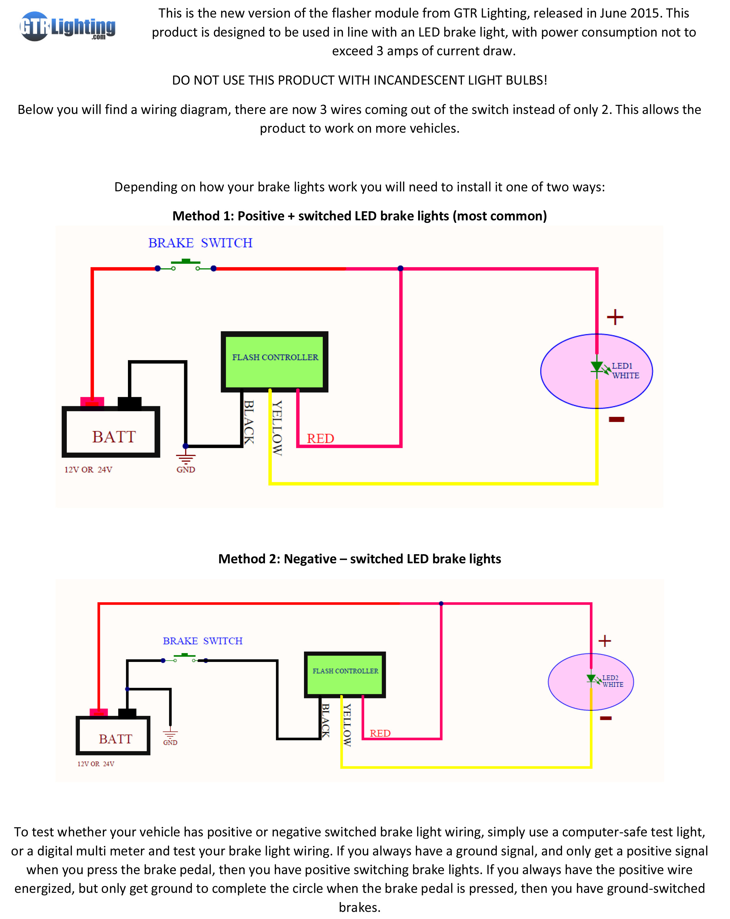
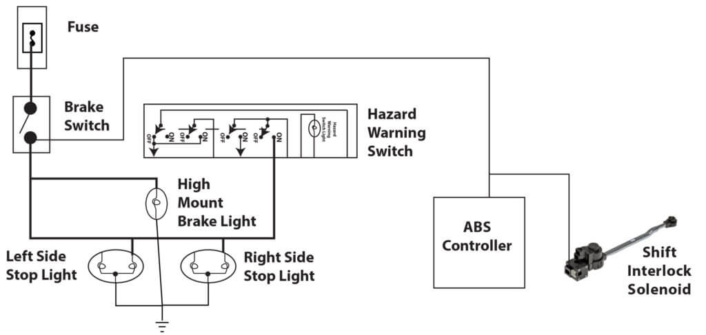
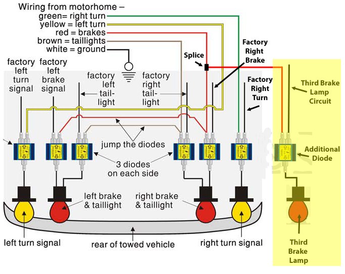
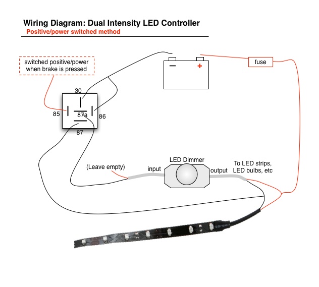
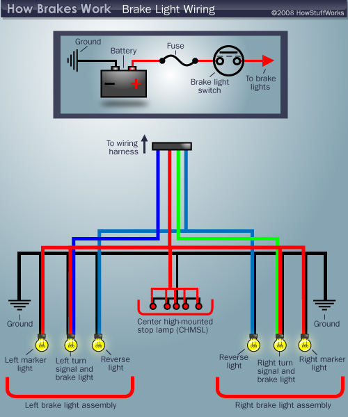
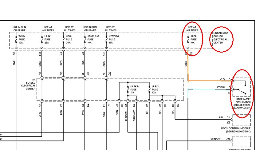
 Title : Third Brake Light Wiring Diagram
Category : Wiring Diagram
Format : PDF
Title : Third Brake Light Wiring Diagram
Category : Wiring Diagram
Format : PDF