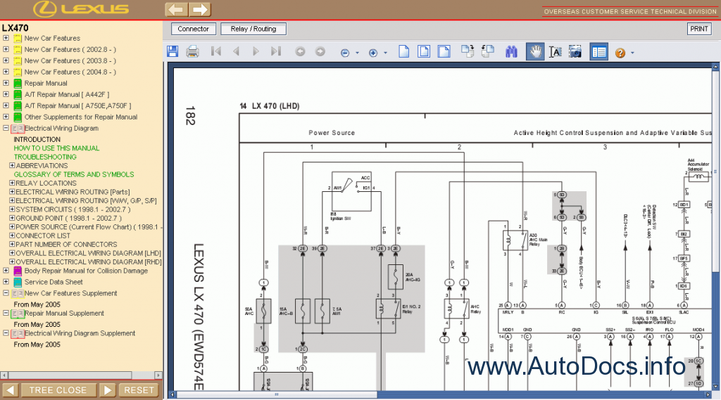
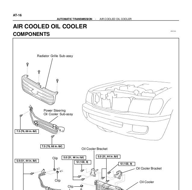
used-2007-lexus-lx-470-suv-pricing-wiring-diagram.pdf
100%

Used 2007 Lexus Lx 470 Suv Pricing Wiring Diagram


HTTP://WIRINGSCHEMA.COM
Revision 2.4 (03/2014)
© 2014 HTTP://WIRINGSCHEMA.COM. All Rights Reserved.

TABLE OF CONTENTS

Cover1
Table of Contents2
Introduction & Scope3
Safety and Handling4
Symbols & Abbreviations5
Wire Colors & Gauges6
Power Distribution Overview7
Grounding Strategy8
Connector Index & Pinout9
Sensor Inputs10
Actuator Outputs11
Control Unit / Module12
Communication Bus13
Protection: Fuse & Relay14
Test Points & References15
Measurement Procedures16
Troubleshooting Guide17
Common Fault Patterns18
Maintenance & Best Practices19
Appendix & References20
Deep Dive #1 - Signal Integrity & EMC21
Deep Dive #2 - Signal Integrity & EMC22
Deep Dive #3 - Signal Integrity & EMC23
Deep Dive #4 - Signal Integrity & EMC24
Deep Dive #5 - Signal Integrity & EMC25
Deep Dive #6 - Signal Integrity & EMC26
Harness Layout Variant #127
Harness Layout Variant #228
Harness Layout Variant #329
Harness Layout Variant #430
Diagnostic Flowchart #131
Diagnostic Flowchart #232
Diagnostic Flowchart #333
Diagnostic Flowchart #434
Case Study #1 - Real-World Failure35
Case Study #2 - Real-World Failure36
Case Study #3 - Real-World Failure37
Case Study #4 - Real-World Failure38
Case Study #5 - Real-World Failure39
Case Study #6 - Real-World Failure40
Hands-On Lab #1 - Measurement Practice41
Hands-On Lab #2 - Measurement Practice42
Hands-On Lab #3 - Measurement Practice43
Hands-On Lab #4 - Measurement Practice44
Hands-On Lab #5 - Measurement Practice45
Hands-On Lab #6 - Measurement Practice46
Checklist & Form #1 - Quality Verification47
Checklist & Form #2 - Quality Verification48
Checklist & Form #3 - Quality Verification49
Checklist & Form #4 - Quality Verification50
Introduction & Scope Page 3

In electrical engineering, precision does not end when the last wire is connected. The long-term safety, reliability, and maintainability of any system depend on how well it is documented, labeled, and verified. Without organized records and consistent labeling, even an advanced control system can become confusing and unsafe within months. Proper records and inspections transform temporary connections into traceable, lasting infrastructure.

### **The Role of Documentation**

Documentation is the written memory of an electrical system. It includes blueprints, circuit diagrams, and update logs that describe how every conductor, fuse, and relay connects and functions. Engineers rely on these records to understand logic, verify safety, and maintain systems.

Accurate documentation begins at the design stage. Each circuit must have a unique identifier that remains the same from software to panel. When changes occurfield modifications or updated componentsthey must be updated instantly in records. A mismatch between paper and physical layout causes delays, confusion, and safety risks.

Modern tools like computer-aided electrical design systems generate uniform diagrams with linked parts data. Many integrate with maintenance databases, linking each component to equipment history and service reports.

### **Labeling and Identification**

Labeling turns documentation into visible reality. Every conductor, connection, and component should be uniquely identified so technicians can work safely without guessing. Proper labeling reduces downtime and improves service quality.

Effective labeling follows these principles:
- **Consistency:** Use a unified numbering system across all panels and drawings.
- **Durability:** Labels must resist UV and mechanical wear. Heat-shrink sleeves, laser engraving, or metal tags last longer than printed labels.
- **Readability:** Font and color contrast should remain legible for years.
- **Traceability:** Every label must correspond directly to schematics.

Color coding adds visual safety. Green-yellow for earth, blue for neutral, red for live remain common, while multi-voltage systems use distinct tones.

### **Inspection and Verification**

Before energizing any system, conduct structured inspection and testing. Typical tests include:
- Line and neutral verification.
- Dielectric integrity testing.
- Voltage-drop or loop-impedance verification.
- Functional testing of control and safety circuits.

All results should be recorded in commissioning reports as the reference for maintenance. Deviations found during tests must lead to immediate rework and record adjustment.

### **Quality-Control Framework**

Quality control (QC) ensures build integrity from material to testing. It starts with incoming inspection of components and wiring materials. Supervisors check termination quality and physical condition. Visual inspections detect damage, looseness, or contamination.

Organizations often follow international quality management systems. These frameworks require evidence for each process and traceable verification. Digital QC systems now allow real-time cloud-based recording. Managers can monitor progress remotely, reducing delays and miscommunication.

### **Change Management and Revision Control**

Electrical systems evolve continuously. Components are upgraded, relocated, or reconfigured over time. Without proper revision control, drawings quickly become outdated. Each modification should include traceable version metadata. As-built drawings must always reflect what exists in realitynot just design intent.

Version control tools synchronize field edits with design teams. This prevents duplicate work and data loss. Historical logs allow engineers to trace failures to their origin.

### **Training and Organizational Culture**

Even the best systems fail without disciplined people. Teams must treat documentation as a mark of engineering pride. Each label, entry, and test report contributes to system knowledge.

Training programs should teach best practices for traceability and revision. Regular audits help sustain accuracy. routine field reviews confirm that labeling matches diagrams. Over time, this builds a culture of precision.

Ultimately, documentation is not paperworkits professionalism. A system that is well-documented, clearly labeled, and routinely verified remains safe, efficient, and serviceable. Good documentation keeps systems alive long after installation ends.

Figure 1
Safety and Handling Page 4

Before opening any panel, disconnect the primary source and confirm zero voltage. Use a meter that has been recently calibrated. If you absolutely must work near live circuits, use insulated tools and keep one hand away from the path. Stay aware of body posture and grounding paths at all times.

When handling components, avoid static discharge by using grounding straps. Do not drag or step on harnesses; abrasion and crushing cause hidden damage. Check crimps for secure grip and signs of corrosion. Follow the manufacturer’s torque specs and connector alignment instructions.

At the end, perform both a visual inspection and an electrical test. Put every cover and shield back on and make sure labels are readable. Do an initial supervised power-up to confirm everything is stable. Responsible handling prevents both short-term accidents and long-term degradation.

Figure 2
Symbols & Abbreviations Page 5

When you know how to read the symbols, you stop guessing and start verifying. A fuse symbol shows you where overcurrent protection lives; a relay symbol shows you where control hands off to power; a diode symbol shows you where current is allowed in only one direction. With just that, you can map logic without removing covers in “Used 2007 Lexus Lx 470 Suv Pricing Wiring Diagram”.

Short codes clarify which of several nearly identical signals you’re looking at. You’ll see tags like O2 UP, O2 DN, FR WSS RH, which tell you not only the sensor type but also the physical location. This is vital when “Used 2007 Lexus Lx 470 Suv Pricing Wiring Diagram” has multiple identical sensors in different positions around the system.

Golden rule in 2025: never “assume what the acronym means.” When in doubt, read the service glossary before applying power — that keeps you from frying expensive modules tied to http://wiringschema.com in Wiring Diagram. Log whatever you probed into https://http://wiringschema.com/used-2007-lexus-lx-470-suv-pricing-wiring-diagram/ so the trace is documented.

Figure 3
Wire Colors & Gauges Page 6

Wire size, measured by its gauge, directly affects how much current it can handle before heat builds up. {Two main systems exist — AWG (American Wire Gauge) and metric square millimeters (mm²).|There are two primary measurement systems: AWG used in North America and mm² used internationally.|Most diagrams list wire size ei...

Using the correct gauge ensures stable readings and prevents dangerous heating inside “Used 2007 Lexus Lx 470 Suv Pricing Wiring Diagram”. {Undersized wires act as resistors, wasting power as heat, while oversized wires add unnecessary bulk and cost.|A wire too small increases resistance and heat; too large increases cost and stiffnes...

Check the printed gauge marking or refer to the manufacturer’s chart under http://wiringschema.com. {If replacements are made in 2025, document the size and route to keep service history traceable in Wiring Diagram.|When repairs occur in 2025, note the wire size and routing details for compliance tracking in Wiring Diagram.|During any 2025 rework, r...

Figure 4
Power Distribution Overview Page 7

Power distribution defines how electrical energy is allocated, controlled, and protected throughout a system.
It maintains voltage stability, current balance, and steady energy delivery to every part of “Used 2007 Lexus Lx 470 Suv Pricing Wiring Diagram”.
A lack of proper power management may result in overheating, unstable current, and equipment failure.
A well-designed power layout organizes energy paths, protects critical devices, and prevents electrical interference.
This structure guarantees that the entire system operates safely and reliably even under demanding conditions.

Building a dependable power system requires detailed calculations and strict adherence to technical standards.
Every conductor and fuse must match its expected current, total length, and tolerance range.
In Wiring Diagram, professionals often refer to ISO 16750, IEC 61000, and SAE J1113 as the baseline for compliance and durability.
Separate high-voltage conductors from signal cables to eliminate electromagnetic crosstalk.
Grounding and fuse terminals must be placed logically to simplify inspection and maintenance.
Good design ensures “Used 2007 Lexus Lx 470 Suv Pricing Wiring Diagram” operates consistently with minimal risk of voltage fluctuation.

Testing and documentation complete the process, guaranteeing lasting quality and reliability.
Engineers must check voltage accuracy, confirm line continuity, and test ground resistance.
All wiring changes must be reflected in schematics and logged in the maintenance database.
All inspection outcomes and documentation must be uploaded to http://wiringschema.com as official records.
Adding 2025 and https://http://wiringschema.com/used-2007-lexus-lx-470-suv-pricing-wiring-diagram/ supports data traceability and historical verification.
This systematic approach ensures that “Used 2007 Lexus Lx 470 Suv Pricing Wiring Diagram” remains safe, compliant, and serviceable throughout its operational lifespan.

Figure 5
Grounding Strategy Page 8

Grounding is the key element that connects electrical systems to the earth, ensuring safety, stability, and long-term reliability.
It serves as a protective barrier against excessive current flow, voltage spikes, and static discharge.
If grounding is poor, “Used 2007 Lexus Lx 470 Suv Pricing Wiring Diagram” can experience voltage instability, interference, and costly hardware failures.
An effective grounding setup ensures excess current is safely redirected into the earth, preventing equipment faults.
Across Wiring Diagram, grounding is a mandatory practice for maintaining reliable and safe electrical systems.

Effective grounding begins with strategic design and detailed preparation.
Before building, engineers need to evaluate soil characteristics, current capacity, and local environment.
Ground joints must be robust, resistant to rust, and tightly integrated into the system.
Within Wiring Diagram, engineers rely on IEC 60364 and IEEE 142 for proper grounding implementation and verification.
All components should be tested to confirm their ability to handle maximum fault current without overheating or failure.
Through these grounding principles, “Used 2007 Lexus Lx 470 Suv Pricing Wiring Diagram” achieves reliability, efficiency, and operational security.

Periodic verification keeps the grounding system reliable and compliant with safety requirements.
Inspectors must test resistance, check joints, and document readings for consistent monitoring.
Damaged or rusted components should be promptly serviced and verified for restored performance.
Maintenance and testing records should be archived to maintain traceability and support safety audits.
Testing schedules should include yearly verification or follow-ups after any electrical change.
By following scheduled inspections, “Used 2007 Lexus Lx 470 Suv Pricing Wiring Diagram” ensures reliable performance and compliance for years.

Figure 6
Connector Index & Pinout Page 9

Used 2007 Lexus Lx 470 Suv Pricing Wiring Diagram Wiring Guide – Connector Index & Pinout Reference 2025

Regular inspection of connectors helps sustain performance and avoids intermittent faults. {Dust, moisture, and vibration are common causes of poor connectivity and short circuits.|Environmental exposure—such as heat and humidity—can degrade connector pins over time.|Loose fittings or o...

Always inspect connector pins and housings visually before assembly to prevent poor contact. {Applying dielectric grease to terminal joints provides additional protection in high-humidity conditions.|Protective compounds help seal terminals from oxygen and water exposure.|Use non-conductive grease to prevent rust...

Only use properly sized adapter pins when checking voltage or continuity on connectors. {Following these maintenance habits helps reduce downtime and keeps the wiring harness in optimal condition.|Preventive connector care ensures consistent current flow and fewer electrical failures.|A disciplined inspection routine exten...

Figure 7
Sensor Inputs Page 10

Used 2007 Lexus Lx 470 Suv Pricing Wiring Diagram Wiring Guide – Sensor Inputs Guide 2025

Manifold Absolute Pressure (MAP) sensors are used to measure air pressure inside the intake manifold. Through pressure feedback, the engine maintains stable combustion and efficient performance.

Most MAP sensors use piezoresistive elements that change resistance under pressure variations. At higher vacuum, output voltage decreases; at lower vacuum, it increases.

A defective MAP sensor might cause black smoke, power loss, or increased fuel consumption. Technicians should inspect hoses and connectors for leaks before replacing the sensor.

Figure 8
Actuator Outputs Page 11

Used 2007 Lexus Lx 470 Suv Pricing Wiring Diagram – Sensor Inputs Guide 2025

Knock detection relies on signal processing from vibration sensors to detect detonation frequencies. {Knock sensors generate voltage signals that correspond to specific vibration patterns.|These signals are filtered and analyzed by the ECU to distinguish true knock from background noise.|Signal processing algorithms ...

Multiple knock sensors may be used in high-performance engines to monitor each cylinder bank. Once stable conditions are achieved, timing is gradually restored for efficiency.

Technicians should ensure correct sensor torque and clean contact surfaces for accurate readings. {Maintaining knock detection systems guarantees efficient combustion and engine protection.|Proper servicing prevents detonation-related damage and maintains engine longevity.|Understanding knock system input logic enhances tuning accurac...

Figure 9
Control Unit / Module Page 12

Used 2007 Lexus Lx 470 Suv Pricing Wiring Diagram Wiring Guide – Actuator Outputs Guide 2025

EGR (Exhaust Gas Recirculation) valves are actuator devices that control the recirculation of exhaust gases. {The EGR valve opens or closes according to ECU commands, adjusting based on engine load and speed.|Modern systems use electric or vacuum-operated actuators to regulate exhaust flow.|Electric EGR valves use st...

Position feedback sensors ensure the ECU knows the exact opening percentage. EGR valves are usually equipped with stepper or DC motor mechanisms for smooth modulation.

Carbon buildup inside the EGR valve is a common failure cause. Regular EGR maintenance improves combustion quality and reduces exhaust pollution.

Figure 10
Communication Bus Page 13

Communication bus systems in Used 2007 Lexus Lx 470 Suv Pricing Wiring Diagram 2025 Wiring Diagram serve as the
coordinated digital backbone that links sensors, actuators, and
electronic control units into a synchronized data environment. Through
structured packet transmission, these networks maintain consistency
across powertrain, chassis, and body domains even under demanding
operating conditions such as thermal expansion, vibration, and
high-speed load transitions.

High-speed CAN governs engine timing, ABS
logic, traction strategies, and other subsystems that require real-time
message exchange, while LIN handles switches and comfort electronics.
FlexRay supports chassis-level precision, and Ethernet transports camera
and radar data with minimal latency.

Communication failures may arise from impedance drift, connector
oxidation, EMI bursts, or degraded shielding, often manifesting as
intermittent sensor dropouts, delayed actuator behavior, or corrupted
frames. Diagnostics require voltage verification, termination checks,
and waveform analysis to isolate the failing segment.

Figure 11
Protection: Fuse & Relay Page 14

Fuse‑relay networks
are engineered as frontline safety components that absorb electrical
anomalies long before they compromise essential subsystems. Through
measured response rates and calibrated cutoff thresholds, they ensure
that power surges, short circuits, and intermittent faults remain
contained within predefined zones. This design philosophy prevents
chain‑reaction failures across distributed ECUs.

In modern architectures, relays handle repetitive activation
cycles, executing commands triggered by sensors or control software.
Their isolation capabilities reduce stress on low‑current circuits,
while fuses provide sacrificial protection whenever load spikes exceed
tolerance thresholds. Together they create a multi‑layer defense grid
adaptable to varying thermal and voltage demands.

Technicians often
diagnose issues by tracking inconsistent current delivery, noisy relay
actuation, unusual voltage fluctuations, or thermal discoloration on
fuse panels. Addressing these problems involves cleaning terminals,
reseating connectors, conditioning ground paths, and confirming load
consumption through controlled testing. Maintaining relay responsiveness
and fuse integrity ensures long‑term electrical stability.

Figure 12
Test Points & References Page 15

Within modern automotive systems,
reference pads act as structured anchor locations for load-induced
voltage collapse, enabling repeatable and consistent measurement
sessions. Their placement across sensor returns, control-module feeds,
and distribution junctions ensures that technicians can evaluate
baseline conditions without interference from adjacent circuits. This
allows diagnostic tools to interpret subsystem health with greater
accuracy.

Technicians rely on these access nodes to conduct high-frequency noise
contamination, waveform pattern checks, and signal-shape verification
across multiple operational domains. By comparing known reference values
against observed readings, inconsistencies can quickly reveal poor
grounding, voltage imbalance, or early-stage conductor fatigue. These
cross-checks are essential when diagnosing sporadic faults that only
appear during thermal expansion cycles or variable-load driving
conditions.

Frequent discoveries made at reference nodes
involve irregular waveform signatures, contact oxidation, fluctuating
supply levels, and mechanical fatigue around connector bodies.
Diagnostic procedures include load simulation, voltage-drop mapping, and
ground potential verification to ensure that each subsystem receives
stable and predictable electrical behavior under all operating
conditions.

Figure 13
Measurement Procedures Page 16

In modern
systems, structured diagnostics rely heavily on dynamic-load voltage
comparison, allowing technicians to capture consistent reference data
while minimizing interference from adjacent circuits. This structured
approach improves accuracy when identifying early deviations or subtle
electrical irregularities within distributed subsystems.

Field evaluations often
incorporate dynamic-load voltage comparison, ensuring comprehensive
monitoring of voltage levels, signal shape, and communication timing.
These measurements reveal hidden failures such as intermittent drops,
loose contacts, or EMI-driven distortions.

Common measurement findings include fluctuating supply rails, irregular
ground returns, unstable sensor signals, and waveform distortion caused
by EMI contamination. Technicians use oscilloscopes, multimeters, and
load probes to isolate these anomalies with precision.

Figure 14
Troubleshooting Guide Page 17

Troubleshooting for Used 2007 Lexus Lx 470 Suv Pricing Wiring Diagram 2025 Wiring Diagram begins with initial
inspection workflow, ensuring the diagnostic process starts with clarity
and consistency. By checking basic system readiness, technicians avoid
deeper misinterpretations.

Technicians use communication-frame timing checks to narrow fault
origins. By validating electrical integrity and observing behavior under
controlled load, they identify abnormal deviations early.

Voltage-drop asymmetry across multi-branch distribution circuits often
signals cumulative connector degradation. Mapping cross-branch
differentials helps locate the failing node.

Figure 15
Common Fault Patterns Page 18

Common fault patterns in Used 2007 Lexus Lx 470 Suv Pricing Wiring Diagram 2025 Wiring Diagram frequently stem from
connector microfractures producing millisecond dropouts, a condition
that introduces irregular electrical behavior observable across multiple
subsystems. Early-stage symptoms are often subtle, manifesting as small
deviations in baseline readings or intermittent inconsistencies that
disappear as quickly as they appear. Technicians must therefore begin
diagnostics with broad-spectrum inspection, ensuring that fundamental
supply and return conditions are stable before interpreting more complex
indicators.

When examining faults tied to connector microfractures producing
millisecond dropouts, technicians often observe fluctuations that
correlate with engine heat, module activation cycles, or environmental
humidity. These conditions can cause reference rails to drift or sensor
outputs to lose linearity, leading to miscommunication between control
units. A structured diagnostic workflow involves comparing real-time
readings to known-good values, replicating environmental conditions, and
isolating behavior changes under controlled load simulations.

Left unresolved, connector microfractures
producing millisecond dropouts may cause cascading failures as modules
attempt to compensate for distorted data streams. This can trigger false
DTCs, unpredictable load behavior, delayed actuator response, and even
safety-feature interruptions. Comprehensive analysis requires reviewing
subsystem interaction maps, recreating stress conditions, and validating
each reference point’s consistency under both static and dynamic
operating states.

Figure 16
Maintenance & Best Practices Page 19

Maintenance and best practices for Used 2007 Lexus Lx 470 Suv Pricing Wiring Diagram 2025 Wiring Diagram place
strong emphasis on long-term wiring lifecycle preservation, ensuring
that electrical reliability remains consistent across all operating
conditions. Technicians begin by examining the harness environment,
verifying routing paths, and confirming that insulation remains intact.
This foundational approach prevents intermittent issues commonly
triggered by heat, vibration, or environmental contamination.

Technicians
analyzing long-term wiring lifecycle preservation typically monitor
connector alignment, evaluate oxidation levels, and inspect wiring for
subtle deformations caused by prolonged thermal exposure. Protective
dielectric compounds and proper routing practices further contribute to
stable electrical pathways that resist mechanical stress and
environmental impact.

Failure
to maintain long-term wiring lifecycle preservation can lead to
cascading electrical inconsistencies, including voltage drops, sensor
signal distortion, and sporadic subsystem instability. Long-term
reliability requires careful documentation, periodic connector service,
and verification of each branch circuit’s mechanical and electrical
health under both static and dynamic conditions.

Figure 17
Appendix & References Page 20

The appendix for Used 2007 Lexus Lx 470 Suv Pricing Wiring Diagram 2025 Wiring Diagram serves as a consolidated
reference hub focused on module identifier lookup tables, offering
technicians consistent terminology and structured documentation
practices. By collecting technical descriptors, abbreviations, and
classification rules into a single section, the appendix streamlines
interpretation of wiring layouts across diverse platforms. This ensures
that even complex circuit structures remain approachable through
standardized definitions and reference cues.

Material within the appendix covering module identifier lookup
tables often features quick‑access charts, terminology groupings, and
definition blocks that serve as anchors during diagnostic work.
Technicians rely on these consolidated references to differentiate
between similar connector profiles, categorize branch circuits, and
verify signal classifications.

Robust appendix material for module identifier lookup tables
strengthens system coherence by standardizing definitions across
numerous technical documents. This reduces ambiguity, supports proper
cataloging of new components, and helps technicians avoid
misinterpretation that could arise from inconsistent reference
structures.

Figure 18
Deep Dive #1 - Signal Integrity & EMC Page 21

Deep analysis of signal integrity in Used 2007 Lexus Lx 470 Suv Pricing Wiring Diagram 2025 Wiring Diagram requires
investigating how RF susceptibility in unshielded sensor cabling
disrupts expected waveform performance across interconnected circuits.
As signals propagate through long harnesses, subtle distortions
accumulate due to impedance shifts, parasitic capacitance, and external
electromagnetic stress. This foundational assessment enables technicians
to understand where integrity loss begins and how it
evolves.

When RF susceptibility in unshielded sensor cabling occurs, signals may
experience phase delays, amplitude decay, or transient ringing depending
on harness composition and environmental exposure. Technicians must
review waveform transitions under varying thermal, load, and EMI
conditions. Tools such as high‑bandwidth oscilloscopes and frequency
analyzers reveal distortion patterns that remain hidden during static
measurements.

If RF susceptibility
in unshielded sensor cabling persists, cascading instability may arise:
intermittent communication, corrupt data frames, or erratic control
logic. Mitigation requires strengthening shielding layers, rebalancing
grounding networks, refining harness layout, and applying proper
termination strategies. These corrective steps restore signal coherence
under EMC stress.

Figure 19
Deep Dive #2 - Signal Integrity & EMC Page 22

Advanced EMC evaluation in Used 2007 Lexus Lx 470 Suv Pricing Wiring Diagram 2025 Wiring Diagram requires close
study of mode-conversion effects in differential signaling, a phenomenon
that can significantly compromise waveform predictability. As systems
scale toward higher bandwidth and greater sensitivity, minor deviations
in signal symmetry or reference alignment become amplified.
Understanding the initial conditions that trigger these distortions
allows technicians to anticipate system vulnerabilities before they
escalate.

Systems experiencing mode-conversion effects
in differential signaling frequently show inconsistencies during fast
state transitions such as ignition sequencing, data bus arbitration, or
actuator modulation. These inconsistencies originate from embedded EMC
interactions that vary with harness geometry, grounding quality, and
cable impedance. Multi‑stage capture techniques help isolate the root
interaction layer.

If left unresolved, mode-conversion effects in
differential signaling may trigger cascading disruptions including frame
corruption, false sensor readings, and irregular module coordination.
Effective countermeasures include controlled grounding, noise‑filter
deployment, re‑termination of critical paths, and restructuring of cable
routing to minimize electromagnetic coupling.

Figure 20
Deep Dive #3 - Signal Integrity & EMC Page 23

A comprehensive
assessment of waveform stability requires understanding the effects of
harmonic resonance buildup under alternating magnetic exposure, a factor
capable of reshaping digital and analog signal profiles in subtle yet
impactful ways. This initial analysis phase helps technicians identify
whether distortions originate from physical harness geometry,
electromagnetic ingress, or internal module reference instability.

Systems experiencing harmonic resonance buildup under
alternating magnetic exposure often show dynamic fluctuations during
transitions such as relay switching, injector activation, or alternator
charging ramps. These transitions inject complex disturbances into
shared wiring paths, making it essential to perform frequency-domain
inspection, spectral decomposition, and transient-load waveform sampling
to fully characterize the EMC interaction.

Prolonged exposure to harmonic resonance buildup under alternating
magnetic exposure may result in cumulative timing drift, erratic
communication retries, or persistent sensor inconsistencies. Mitigation
strategies include rebalancing harness impedance, reinforcing shielding
layers, deploying targeted EMI filters, optimizing grounding topology,
and refining cable routing to minimize exposure to EMC hotspots. These
measures restore signal clarity and long-term subsystem reliability.

Figure 21
Deep Dive #4 - Signal Integrity & EMC Page 24

Evaluating advanced signal‑integrity interactions involves
examining the influence of voltage-transient stacking during rapid
load‑switching events, a phenomenon capable of inducing significant
waveform displacement. These disruptions often develop gradually,
becoming noticeable only when communication reliability begins to drift
or subsystem timing loses coherence.

When voltage-transient stacking during rapid load‑switching events is
active, waveform distortion may manifest through amplitude instability,
reference drift, unexpected ringing artifacts, or shifting propagation
delays. These effects often correlate with subsystem transitions,
thermal cycles, actuator bursts, or environmental EMI fluctuations.
High‑bandwidth test equipment reveals the microscopic deviations hidden
within normal signal envelopes.

If unresolved, voltage-transient stacking
during rapid load‑switching events may escalate into severe operational
instability, corrupting digital frames or disrupting tight‑timing
control loops. Effective mitigation requires targeted filtering,
optimized termination schemes, strategic rerouting, and harmonic
suppression tailored to the affected frequency bands.

Figure 22
Deep Dive #5 - Signal Integrity & EMC Page 25

In-depth signal integrity analysis requires
understanding how cross-domain EMI accumulation during multi-actuator
operation influences propagation across mixed-frequency network paths.
These distortions may remain hidden during low-load conditions, only
becoming evident when multiple modules operate simultaneously or when
thermal boundaries shift.

When cross-domain EMI accumulation during multi-actuator operation is
active, signal paths may exhibit ringing artifacts, asymmetric edge
transitions, timing drift, or unexpected amplitude compression. These
effects are amplified during actuator bursts, ignition sequencing, or
simultaneous communication surges. Technicians rely on high-bandwidth
oscilloscopes and spectral analysis to characterize these distortions
accurately.

If left unresolved, cross-domain EMI accumulation
during multi-actuator operation may evolve into severe operational
instability—ranging from data corruption to sporadic ECU
desynchronization. Effective countermeasures include refining harness
geometry, isolating radiated hotspots, enhancing return-path uniformity,
and implementing frequency-specific suppression techniques.

Figure 23
Deep Dive #6 - Signal Integrity & EMC Page 26

Advanced EMC analysis in Used 2007 Lexus Lx 470 Suv Pricing Wiring Diagram 2025 Wiring Diagram must consider
dielectric absorption altering waveform stability in composite
insulation materials, a complex interaction capable of reshaping
waveform integrity across numerous interconnected subsystems. As modern
vehicles integrate high-speed communication layers, ADAS modules, EV
power electronics, and dense mixed-signal harness routing, even subtle
non-linear effects can disrupt deterministic timing and system
reliability.

When dielectric absorption altering waveform stability in composite
insulation materials occurs, technicians may observe inconsistent
rise-times, amplitude drift, complex ringing patterns, or intermittent
jitter artifacts. These symptoms often appear during subsystem
interactions—such as inverter ramps, actuator bursts, ADAS
synchronization cycles, or ground-potential fluctuations. High-bandwidth
oscilloscopes and spectrum analyzers reveal hidden distortion
signatures.

Long-term exposure to dielectric absorption altering waveform stability
in composite insulation materials may degrade subsystem coherence,
trigger inconsistent module responses, corrupt data frames, or produce
rare but severe system anomalies. Mitigation strategies include
optimized shielding architecture, targeted filter deployment, rerouting
vulnerable harness paths, reinforcing isolation barriers, and ensuring
ground uniformity throughout critical return networks.

Figure 24
Harness Layout Variant #1 Page 27

In-depth planning of
harness architecture involves understanding how mounting‑clip geometry
affecting long-term harness stability affects long-term stability. As
wiring systems grow more complex, engineers must consider structural
constraints, subsystem interaction, and the balance between electrical
separation and mechanical compactness.

During layout development, mounting‑clip geometry affecting long-term
harness stability can determine whether circuits maintain clean signal
behavior under dynamic operating conditions. Mechanical and electrical
domains intersect heavily in modern harness designs—routing angle,
bundling tightness, grounding alignment, and mounting intervals all
affect susceptibility to noise, wear, and heat.

Proper control of mounting‑clip geometry affecting long-term harness
stability ensures reliable operation, simplified manufacturing, and
long-term durability. Technicians and engineers apply routing
guidelines, shielding rules, and structural anchoring principles to
ensure consistent performance regardless of environment or subsystem
load.

Figure 25
Harness Layout Variant #2 Page 28

Harness Layout Variant #2 for Used 2007 Lexus Lx 470 Suv Pricing Wiring Diagram 2025 Wiring Diagram focuses on
anti-chafe barrier positioning for vibration zones, a structural and
electrical consideration that influences both reliability and long-term
stability. As modern vehicles integrate more electronic modules, routing
strategies must balance physical constraints with the need for
predictable signal behavior.

In real-world conditions, anti-chafe barrier positioning for
vibration zones determines the durability of the harness against
temperature cycles, motion-induced stress, and subsystem interference.
Careful arrangement of connectors, bundling layers, and anti-chafe
supports helps maintain reliable performance even in high-demand chassis
zones.

Managing anti-chafe barrier positioning for vibration zones effectively
results in improved robustness, simplified maintenance, and enhanced
overall system stability. Engineers apply isolation rules, structural
reinforcement, and optimized routing logic to produce a layout capable
of sustaining long-term operational loads.

Figure 26
Harness Layout Variant #3 Page 29

Engineering Harness Layout
Variant #3 involves assessing how service‑optimized harness loops for
diagnostic accessibility influences subsystem spacing, EMI exposure,
mounting geometry, and overall routing efficiency. As harness density
increases, thoughtful initial planning becomes critical to prevent
premature system fatigue.

During refinement, service‑optimized harness loops for diagnostic
accessibility can impact vibration resistance, shielding effectiveness,
ground continuity, and stress distribution along key segments. Designers
analyze bundle thickness, elevation shifts, structural transitions, and
separation from high‑interference components to optimize both mechanical
and electrical performance.

If not addressed,
service‑optimized harness loops for diagnostic accessibility may lead to
premature insulation wear, abrasion hotspots, intermittent electrical
noise, or connector fatigue. Balanced tensioning, routing symmetry, and
strategic material selection significantly mitigate these risks across
all major vehicle subsystems.

Figure 27
Harness Layout Variant #4 Page 30

Harness Layout Variant #4 for Used 2007 Lexus Lx 470 Suv Pricing Wiring Diagram 2025 Wiring Diagram emphasizes roof-line harness suspension minimizing sag
and rattle, combining mechanical and electrical considerations to maintain cable stability across multiple
vehicle zones. Early planning defines routing elevation, clearance from heat sources, and anchoring points so
each branch can absorb vibration and thermal expansion without overstressing connectors.

During
refinement, roof-line harness suspension minimizing sag and rattle influences grommet placement, tie-point
spacing, and bend-radius decisions. These parameters determine whether the harness can endure heat cycles,
structural motion, and chassis vibration. Power–data separation rules, ground-return alignment, and shielding-
zone allocation help suppress interference without hindering manufacturability.

Proper control of roof-line harness suspension minimizing sag and rattle
minimizes moisture intrusion, terminal corrosion, and cross-path noise. Best practices include labeled
manufacturing references, measured service loops, and HV/LV clearance audits. When components are updated,
route documentation and measurement points simplify verification without dismantling the entire assembly.

Figure 28
Diagnostic Flowchart #1 Page 31

The initial stage of
Diagnostic Flowchart #1 emphasizes controlled short‑circuit isolation using staged segmentation, ensuring that
the most foundational electrical references are validated before branching into deeper subsystem evaluation.
This reduces misdirection caused by surface‑level symptoms. Mid‑stage analysis integrates controlled
short‑circuit isolation using staged segmentation into a structured decision tree, allowing each measurement
to eliminate specific classes of faults. By progressively narrowing the fault domain, the technician
accelerates isolation of underlying issues such as inconsistent module timing, weak grounds, or intermittent
sensor behavior. A complete
validation cycle ensures controlled short‑circuit isolation using staged segmentation is confirmed across all
operational states. Documenting each decision point creates traceability, enabling faster future diagnostics
and reducing the chance of repeat failures.

Figure 29
Diagnostic Flowchart #2 Page 32

The initial phase of Diagnostic Flowchart #2 emphasizes interactive
load‑step testing for marginal connectors, ensuring that technicians validate foundational electrical
relationships before evaluating deeper subsystem interactions. This prevents diagnostic drift and reduces
unnecessary component replacements. Throughout the flowchart,
interactive load‑step testing for marginal connectors interacts with verification procedures involving
reference stability, module synchronization, and relay or fuse behavior. Each decision point eliminates entire
categories of possible failures, allowing the technician to converge toward root cause faster. Completing
the flow ensures that interactive load‑step testing for marginal connectors is validated under multiple
operating conditions, reducing the likelihood of recurring issues. The resulting diagnostic trail provides
traceable documentation that improves future troubleshooting accuracy.

Figure 30
Diagnostic Flowchart #3 Page 33

The first branch of Diagnostic Flowchart #3 prioritizes tiered
decision‑tree confirmation for cascading electrical faults, ensuring foundational stability is confirmed
before deeper subsystem exploration. This prevents misdirection caused by intermittent or misleading
electrical behavior. As the flowchart progresses, tiered decision‑tree confirmation for cascading
electrical faults defines how mid‑stage decisions are segmented. Technicians sequentially eliminate power,
ground, communication, and actuation domains while interpreting timing shifts, signal drift, or misalignment
across related circuits. If tiered decision‑tree confirmation for cascading
electrical faults is not thoroughly verified, hidden electrical inconsistencies may trigger cascading
subsystem faults. A reinforced decision‑tree process ensures all potential contributors are validated.

Figure 31
Diagnostic Flowchart #4 Page 34

Diagnostic Flowchart #4 for Used 2007 Lexus Lx 470 Suv Pricing Wiring Diagram 2025
Wiring Diagram focuses on tri‑layer voltage reference evaluation under load, laying the foundation for a structured
fault‑isolation path that eliminates guesswork and reduces unnecessary component swapping. The first stage
examines core references, voltage stability, and baseline communication health to determine whether the issue
originates in the primary network layer or in a secondary subsystem. Technicians follow a branched decision
flow that evaluates signal symmetry, grounding patterns, and frame stability before advancing into deeper
diagnostic layers. As the evaluation continues, tri‑layer voltage reference evaluation under load becomes
the controlling factor for mid‑level branch decisions. This includes correlating waveform alignment,
identifying momentary desync signatures, and interpreting module wake‑timing conflicts. By dividing the
diagnostic pathway into focused electrical domains—power delivery, grounding integrity, communication
architecture, and actuator response—the flowchart ensures that each stage removes entire categories of faults
with minimal overlap. This structured segmentation accelerates troubleshooting and increases diagnostic
precision. The final stage ensures that tri‑layer voltage
reference evaluation under load is validated under multiple operating conditions, including thermal stress,
load spikes, vibration, and state transitions. These controlled stress points help reveal hidden instabilities
that may not appear during static testing. Completing all verification nodes ensures long‑term stability,
reducing the likelihood of recurring issues and enabling technicians to document clear, repeatable steps for
future diagnostics.

Figure 32
Case Study #1 - Real-World Failure Page 35

Case Study #1 for Used 2007 Lexus Lx 470 Suv Pricing Wiring Diagram 2025 Wiring Diagram examines a real‑world failure involving ABS wheel‑speed signal
dropout due to shield abrasion. The issue first appeared as an intermittent symptom that did not trigger a
consistent fault code, causing technicians to suspect unrelated components. Early observations highlighted
irregular electrical behavior, such as momentary signal distortion, delayed module responses, or fluctuating
reference values. These symptoms tended to surface under specific thermal, vibration, or load conditions,
making replication difficult during static diagnostic tests. Further investigation into ABS wheel‑speed
signal dropout due to shield abrasion required systematic measurement across power distribution paths,
grounding nodes, and communication channels. Technicians used targeted diagnostic flowcharts to isolate
variables such as voltage drop, EMI exposure, timing skew, and subsystem desynchronization. By reproducing the
fault under controlled conditions—applying heat, inducing vibration, or simulating high load—they identified
the precise moment the failure manifested. This structured process eliminated multiple potential contributors,
narrowing the fault domain to a specific harness segment, component group, or module logic pathway. The
confirmed cause tied to ABS wheel‑speed signal dropout due to shield abrasion allowed technicians to implement
the correct repair, whether through component replacement, harness restoration, recalibration, or module
reprogramming. After corrective action, the system was subjected to repeated verification cycles to ensure
long‑term stability under all operating conditions. Documenting the failure pattern and diagnostic sequence
provided valuable reference material for similar future cases, reducing diagnostic time and preventing
unnecessary part replacement.

Figure 33
Case Study #2 - Real-World Failure Page 36

Case Study #2 for Used 2007 Lexus Lx 470 Suv Pricing Wiring Diagram 2025 Wiring Diagram examines a real‑world failure involving engine‑cooling module
performance drop caused by harness tension fatigue. The issue presented itself with intermittent symptoms that
varied depending on temperature, load, or vehicle motion. Technicians initially observed irregular system
responses, inconsistent sensor readings, or sporadic communication drops. Because the symptoms did not follow
a predictable pattern, early attempts at replication were unsuccessful, leading to misleading assumptions
about unrelated subsystems. A detailed investigation into engine‑cooling module performance drop caused by
harness tension fatigue required structured diagnostic branching that isolated power delivery, ground
stability, communication timing, and sensor integrity. Using controlled diagnostic tools, technicians applied
thermal load, vibration, and staged electrical demand to recreate the failure in a measurable environment.
Progressive elimination of subsystem groups—ECUs, harness segments, reference points, and actuator
pathways—helped reveal how the failure manifested only under specific operating thresholds. This systematic
breakdown prevented misdiagnosis and reduced unnecessary component swaps. Once the cause linked to
engine‑cooling module performance drop caused by harness tension fatigue was confirmed, the corrective action
involved either reconditioning the harness, replacing the affected component, reprogramming module firmware,
or adjusting calibration parameters. Post‑repair validation cycles were performed under varied conditions to
ensure long‑term reliability and prevent future recurrence. Documentation of the failure characteristics,
diagnostic sequence, and final resolution now serves as a reference for addressing similar complex faults more
efficiently.

Figure 34
Case Study #3 - Real-World Failure Page 37

Case Study #3 for Used 2007 Lexus Lx 470 Suv Pricing Wiring Diagram 2025 Wiring Diagram focuses on a real‑world failure involving harness shielding
collapse resulting in broadband EMI intrusion. Technicians first observed erratic system behavior, including
fluctuating sensor values, delayed control responses, and sporadic communication warnings. These symptoms
appeared inconsistently, often only under specific temperature, load, or vibration conditions. Early
troubleshooting attempts failed to replicate the issue reliably, creating the impression of multiple unrelated
subsystem faults rather than a single root cause. To investigate harness shielding collapse resulting in
broadband EMI intrusion, a structured diagnostic approach was essential. Technicians conducted staged power
and ground validation, followed by controlled stress testing that included thermal loading, vibration
simulation, and alternating electrical demand. This method helped reveal the precise operational threshold at
which the failure manifested. By isolating system domains—communication networks, power rails, grounding
nodes, and actuator pathways—the diagnostic team progressively eliminated misleading symptoms and narrowed the
problem to a specific failure mechanism. After identifying the underlying cause tied to harness shielding
collapse resulting in broadband EMI intrusion, technicians carried out targeted corrective actions such as
replacing compromised components, restoring harness integrity, updating ECU firmware, or recalibrating
affected subsystems. Post‑repair validation cycles confirmed stable performance across all operating
conditions. The documented diagnostic path and resolution now serve as a repeatable reference for addressing
similar failures with greater speed and accuracy.

Figure 35
Case Study #4 - Real-World Failure Page 38

Case Study #4 for Used 2007 Lexus Lx 470 Suv Pricing Wiring Diagram 2025 Wiring Diagram examines a high‑complexity real‑world failure involving sensor
resolution collapse during high‑frequency vibration exposure. The issue manifested across multiple subsystems
simultaneously, creating an array of misleading symptoms ranging from inconsistent module responses to
distorted sensor feedback and intermittent communication warnings. Initial diagnostics were inconclusive due
to the fault’s dependency on vibration, thermal shifts, or rapid load changes. These fluctuating conditions
allowed the failure to remain dormant during static testing, pushing technicians to explore deeper system
interactions that extended beyond conventional troubleshooting frameworks. To investigate sensor resolution
collapse during high‑frequency vibration exposure, technicians implemented a layered diagnostic workflow
combining power‑rail monitoring, ground‑path validation, EMI tracing, and logic‑layer analysis. Stress tests
were applied in controlled sequences to recreate the precise environment in which the instability
surfaced—often requiring synchronized heat, vibration, and electrical load modulation. By isolating
communication domains, verifying timing thresholds, and comparing analog sensor behavior under dynamic
conditions, the diagnostic team uncovered subtle inconsistencies that pointed toward deeper system‑level
interactions rather than isolated component faults. After confirming the root mechanism tied to sensor
resolution collapse during high‑frequency vibration exposure, corrective action involved component
replacement, harness reconditioning, ground‑plane reinforcement, or ECU firmware restructuring depending on
the failure’s nature. Technicians performed post‑repair endurance tests that included repeated thermal
cycling, vibration exposure, and electrical stress to guarantee long‑term system stability. Thorough
documentation of the analysis method, failure pattern, and final resolution now serves as a highly valuable
reference for identifying and mitigating similar high‑complexity failures in the future.

Figure 36
Case Study #5 - Real-World Failure Page 39

Case Study #5 for Used 2007 Lexus Lx 470 Suv Pricing Wiring Diagram 2025 Wiring Diagram investigates a complex real‑world failure involving PWM carrier
interference creating actuator response instability. The issue initially presented as an inconsistent mixture
of delayed system reactions, irregular sensor values, and sporadic communication disruptions. These events
tended to appear under dynamic operational conditions—such as elevated temperatures, sudden load transitions,
or mechanical vibration—which made early replication attempts unreliable. Technicians encountered symptoms
occurring across multiple modules simultaneously, suggesting a deeper systemic interaction rather than a
single isolated component failure. During the investigation of PWM carrier interference creating actuator
response instability, a multi‑layered diagnostic workflow was deployed. Technicians performed sequential
power‑rail mapping, ground‑plane verification, and high‑frequency noise tracing to detect hidden
instabilities. Controlled stress testing—including targeted heat application, induced vibration, and variable
load modulation—was carried out to reproduce the failure consistently. The team methodically isolated
subsystem domains such as communication networks, analog sensor paths, actuator control logic, and module
synchronization timing. This progressive elimination approach identified critical operational thresholds where
the failure reliably emerged. After determining the underlying mechanism tied to PWM carrier interference
creating actuator response instability, technicians carried out corrective actions that ranged from harness
reconditioning and connector reinforcement to firmware restructuring and recalibration of affected modules.
Post‑repair validation involved repeated cycles of vibration, thermal stress, and voltage fluctuation to
ensure long‑term stability and eliminate the possibility of recurrence. The documented resolution pathway now
serves as an advanced reference model for diagnosing similarly complex failures across modern vehicle
platforms.

Figure 37
Case Study #6 - Real-World Failure Page 40

Case Study #6 for Used 2007 Lexus Lx 470 Suv Pricing Wiring Diagram 2025 Wiring Diagram examines a complex real‑world failure involving gateway arbitration
stalls during dense multi‑channel CAN traffic. Symptoms emerged irregularly, with clustered faults appearing
across unrelated modules, giving the impression of multiple simultaneous subsystem failures. These
irregularities depended strongly on vibration, temperature shifts, or abrupt electrical load changes, making
the issue difficult to reproduce during initial diagnostic attempts. Technicians noted inconsistent sensor
feedback, communication delays, and momentary power‑rail fluctuations that persisted without generating
definitive fault codes. The investigation into gateway arbitration stalls during dense multi‑channel CAN
traffic required a multi‑layer diagnostic strategy combining signal‑path tracing, ground stability assessment,
and high‑frequency noise evaluation. Technicians executed controlled stress tests—including thermal cycling,
vibration induction, and staged electrical loading—to reveal the exact thresholds at which the fault
manifested. Using structured elimination across harness segments, module clusters, and reference nodes, they
isolated subtle timing deviations, analog distortions, or communication desynchronization that pointed toward
a deeper systemic failure mechanism rather than isolated component malfunction. Once gateway arbitration
stalls during dense multi‑channel CAN traffic was identified as the root failure mechanism, targeted
corrective measures were implemented. These included harness reinforcement, connector replacement, firmware
restructuring, recalibration of key modules, or ground‑path reconfiguration depending on the nature of the
instability. Post‑repair endurance runs with repeated vibration, heat cycles, and voltage stress ensured
long‑term reliability. Documentation of the diagnostic sequence and recovery pathway now provides a vital
reference for detecting and resolving similarly complex failures more efficiently in future service
operations.

Figure 38
Hands-On Lab #1 - Measurement Practice Page 41

Hands‑On Lab #1 for Used 2007 Lexus Lx 470 Suv Pricing Wiring Diagram 2025 Wiring Diagram focuses on gateway throughput measurement under diagnostic
traffic load. This exercise teaches technicians how to perform structured diagnostic measurements using
multimeters, oscilloscopes, current probes, and differential tools. The initial phase emphasizes establishing
a stable baseline by checking reference voltages, verifying continuity, and confirming ground integrity. These
foundational steps ensure that subsequent measurements reflect true system behavior rather than secondary
anomalies introduced by poor probing technique or unstable electrical conditions. During the measurement
routine for gateway throughput measurement under diagnostic traffic load, technicians analyze dynamic behavior
by applying controlled load, capturing waveform transitions, and monitoring subsystem responses. This includes
observing timing shifts, duty‑cycle changes, ripple patterns, or communication irregularities. By replicating
real operating conditions—thermal changes, vibration, or electrical demand spikes—technicians gain insight
into how the system behaves under stress. This approach allows deeper interpretation of patterns that static
readings cannot reveal. After completing the procedure for gateway throughput measurement under diagnostic
traffic load, results are documented with precise measurement values, waveform captures, and interpretation
notes. Technicians compare the observed data with known good references to determine whether performance falls
within acceptable thresholds. The collected information not only confirms system health but also builds
long‑term diagnostic proficiency by helping technicians recognize early indicators of failure and understand
how small variations can evolve into larger issues.

Figure 39
Hands-On Lab #2 - Measurement Practice Page 42

Hands‑On Lab #2 for Used 2007 Lexus Lx 470 Suv Pricing Wiring Diagram 2025 Wiring Diagram focuses on thermal drift measurement in manifold pressure
sensors. This practical exercise expands technician measurement skills by emphasizing accurate probing
technique, stable reference validation, and controlled test‑environment setup. Establishing baseline
readings—such as reference ground, regulated voltage output, and static waveform characteristics—is essential
before any dynamic testing occurs. These foundational checks prevent misinterpretation caused by poor tool
placement, floating grounds, or unstable measurement conditions. During the procedure for thermal drift
measurement in manifold pressure sensors, technicians simulate operating conditions using thermal stress,
vibration input, and staged subsystem loading. Dynamic measurements reveal timing inconsistencies, amplitude
drift, duty‑cycle changes, communication irregularities, or nonlinear sensor behavior. Oscilloscopes, current
probes, and differential meters are used to capture high‑resolution waveform data, enabling technicians to
identify subtle deviations that static multimeter readings cannot detect. Emphasis is placed on interpreting
waveform shape, slope, ripple components, and synchronization accuracy across interacting modules. After
completing the measurement routine for thermal drift measurement in manifold pressure sensors, technicians
document quantitative findings—including waveform captures, voltage ranges, timing intervals, and noise
signatures. The recorded results are compared to known‑good references to determine subsystem health and
detect early‑stage degradation. This structured approach not only builds diagnostic proficiency but also
enhances a technician’s ability to predict emerging faults before they manifest as critical failures,
strengthening long‑term reliability of the entire system.

Figure 40
Hands-On Lab #3 - Measurement Practice Page 43

Hands‑On Lab #3 for Used 2007 Lexus Lx 470 Suv Pricing Wiring Diagram 2025 Wiring Diagram focuses on CAN transceiver edge‑rate evaluation using
differential probing. This exercise trains technicians to establish accurate baseline measurements before
introducing dynamic stress. Initial steps include validating reference grounds, confirming supply‑rail
stability, and ensuring probing accuracy. These fundamentals prevent distorted readings and help ensure that
waveform captures or voltage measurements reflect true electrical behavior rather than artifacts caused by
improper setup or tool noise. During the diagnostic routine for CAN transceiver edge‑rate evaluation using
differential probing, technicians apply controlled environmental adjustments such as thermal cycling,
vibration, electrical loading, and communication traffic modulation. These dynamic inputs help expose timing
drift, ripple growth, duty‑cycle deviations, analog‑signal distortion, or module synchronization errors.
Oscilloscopes, clamp meters, and differential probes are used extensively to capture transitional data that
cannot be observed with static measurements alone. After completing the measurement sequence for CAN
transceiver edge‑rate evaluation using differential probing, technicians document waveform characteristics,
voltage ranges, current behavior, communication timing variations, and noise patterns. Comparison with
known‑good datasets allows early detection of performance anomalies and marginal conditions. This structured
measurement methodology strengthens diagnostic confidence and enables technicians to identify subtle
degradation before it becomes a critical operational failure.

Figure 41
Hands-On Lab #4 - Measurement Practice Page 44

Hands‑On Lab #4 for Used 2007 Lexus Lx 470 Suv Pricing Wiring Diagram 2025 Wiring Diagram focuses on starter‑current waveform profiling during cold‑start
conditions. This laboratory exercise builds on prior modules by emphasizing deeper measurement accuracy,
environment control, and test‑condition replication. Technicians begin by validating stable reference grounds,
confirming regulated supply integrity, and preparing measurement tools such as oscilloscopes, current probes,
and high‑bandwidth differential probes. Establishing clean baselines ensures that subsequent waveform analysis
is meaningful and not influenced by tool noise or ground drift. During the measurement procedure for
starter‑current waveform profiling during cold‑start conditions, technicians introduce dynamic variations
including staged electrical loading, thermal cycling, vibration input, or communication‑bus saturation. These
conditions reveal real‑time behaviors such as timing drift, amplitude instability, duty‑cycle deviation,
ripple formation, or synchronization loss between interacting modules. High‑resolution waveform capture
enables technicians to observe subtle waveform features—slew rate, edge deformation, overshoot, undershoot,
noise bursts, and harmonic artifacts. Upon completing the assessment for starter‑current waveform profiling
during cold‑start conditions, all findings are documented with waveform snapshots, quantitative measurements,
and diagnostic interpretations. Comparing collected data with verified reference signatures helps identify
early‑stage degradation, marginal component performance, and hidden instability trends. This rigorous
measurement framework strengthens diagnostic precision and ensures that technicians can detect complex
electrical issues long before they evolve into system‑wide failures.

Figure 42
Hands-On Lab #5 - Measurement Practice Page 45

Hands‑On Lab #5 for Used 2007 Lexus Lx 470 Suv Pricing Wiring Diagram 2025 Wiring Diagram focuses on oxygen‑sensor output latency during rapid lambda
transitions. The session begins with establishing stable measurement baselines by validating grounding
integrity, confirming supply‑rail stability, and ensuring probe calibration. These steps prevent erroneous
readings and ensure that all waveform captures accurately reflect subsystem behavior. High‑accuracy tools such
as oscilloscopes, clamp meters, and differential probes are prepared to avoid ground‑loop artifacts or
measurement noise. During the procedure for oxygen‑sensor output latency during rapid lambda transitions,
technicians introduce dynamic test conditions such as controlled load spikes, thermal cycling, vibration, and
communication saturation. These deliberate stresses expose real‑time effects like timing jitter, duty‑cycle
deformation, signal‑edge distortion, ripple growth, and cross‑module synchronization drift. High‑resolution
waveform captures allow technicians to identify anomalies that static tests cannot reveal, such as harmonic
noise, high‑frequency interference, or momentary dropouts in communication signals. After completing all
measurements for oxygen‑sensor output latency during rapid lambda transitions, technicians document voltage
ranges, timing intervals, waveform shapes, noise signatures, and current‑draw curves. These results are
compared against known‑good references to identify early‑stage degradation or marginal component behavior.
Through this structured measurement framework, technicians strengthen diagnostic accuracy and develop
long‑term proficiency in detecting subtle trends that could lead to future system failures.

Figure 43
Hands-On Lab #6 - Measurement Practice Page 46

Hands‑On Lab #6 for Used 2007 Lexus Lx 470 Suv Pricing Wiring Diagram 2025 Wiring Diagram focuses on ECU power‑rail ripple signature profiling via FFT
inspection. This advanced laboratory module strengthens technician capability in capturing high‑accuracy
diagnostic measurements. The session begins with baseline validation of ground reference integrity, regulated
supply behavior, and probe calibration. Ensuring noise‑free, stable baselines prevents waveform distortion and
guarantees that all readings reflect genuine subsystem behavior rather than tool‑induced artifacts or
grounding errors. Technicians then apply controlled environmental modulation such as thermal shocks,
vibration exposure, staged load cycling, and communication traffic saturation. These dynamic conditions reveal
subtle faults including timing jitter, duty‑cycle deformation, amplitude fluctuation, edge‑rate distortion,
harmonic buildup, ripple amplification, and module synchronization drift. High‑bandwidth oscilloscopes,
differential probes, and current clamps are used to capture transient behaviors invisible to static multimeter
measurements. Following completion of the measurement routine for ECU power‑rail ripple signature profiling
via FFT inspection, technicians document waveform shapes, voltage windows, timing offsets, noise signatures,
and current patterns. Results are compared against validated reference datasets to detect early‑stage
degradation or marginal component behavior. By mastering this structured diagnostic framework, technicians
build long‑term proficiency and can identify complex electrical instabilities before they lead to full system
failure.

Figure 44
Checklist & Form #1 - Quality Verification Page 47

Checklist & Form #1 for Used 2007 Lexus Lx 470 Suv Pricing Wiring Diagram 2025 Wiring Diagram focuses on noise‑susceptibility audit for analog and digital
lines. This verification document provides a structured method for ensuring electrical and electronic
subsystems meet required performance standards. Technicians begin by confirming baseline conditions such as
stable reference grounds, regulated voltage supplies, and proper connector engagement. Establishing these
baselines prevents false readings and ensures all subsequent measurements accurately reflect system behavior.
During completion of this form for noise‑susceptibility audit for analog and digital lines, technicians
evaluate subsystem performance under both static and dynamic conditions. This includes validating signal
integrity, monitoring voltage or current drift, assessing noise susceptibility, and confirming communication
stability across modules. Checkpoints guide technicians through critical inspection areas—sensor accuracy,
actuator responsiveness, bus timing, harness quality, and module synchronization—ensuring each element is
validated thoroughly using industry‑standard measurement practices. After filling out the checklist for
noise‑susceptibility audit for analog and digital lines, all results are documented, interpreted, and compared
against known‑good reference values. This structured documentation supports long‑term reliability tracking,
facilitates early detection of emerging issues, and strengthens overall system quality. The completed form
becomes part of the quality‑assurance record, ensuring compliance with technical standards and providing
traceability for future diagnostics.

Figure 45
Checklist & Form #2 - Quality Verification Page 48

Checklist & Form #2 for Used 2007 Lexus Lx 470 Suv Pricing Wiring Diagram 2025 Wiring Diagram focuses on ECU input‑voltage stability verification form.
This structured verification tool guides technicians through a comprehensive evaluation of electrical system
readiness. The process begins by validating baseline electrical conditions such as stable ground references,
regulated supply integrity, and secure connector engagement. Establishing these fundamentals ensures that all
subsequent diagnostic readings reflect true subsystem behavior rather than interference from setup or tooling
issues. While completing this form for ECU input‑voltage stability verification form, technicians examine
subsystem performance across both static and dynamic conditions. Evaluation tasks include verifying signal
consistency, assessing noise susceptibility, monitoring thermal drift effects, checking communication timing
accuracy, and confirming actuator responsiveness. Each checkpoint guides the technician through critical areas
that contribute to overall system reliability, helping ensure that performance remains within specification
even during operational stress. After documenting all required fields for ECU input‑voltage stability
verification form, technicians interpret recorded measurements and compare them against validated reference
datasets. This documentation provides traceability, supports early detection of marginal conditions, and
strengthens long‑term quality control. The completed checklist forms part of the official audit trail and
contributes directly to maintaining electrical‑system reliability across the vehicle platform.

Figure 46
Checklist & Form #3 - Quality Verification Page 49

Checklist & Form #3 for Used 2007 Lexus Lx 470 Suv Pricing Wiring Diagram 2025 Wiring Diagram covers sensor‑feedback reliability confirmation sheet. This
verification document ensures that every subsystem meets electrical and operational requirements before final
approval. Technicians begin by validating fundamental conditions such as regulated supply voltage, stable
ground references, and secure connector seating. These baseline checks eliminate misleading readings and
ensure that all subsequent measurements represent true subsystem behavior without tool‑induced artifacts.
While completing this form for sensor‑feedback reliability confirmation sheet, technicians review subsystem
behavior under multiple operating conditions. This includes monitoring thermal drift, verifying
signal‑integrity consistency, checking module synchronization, assessing noise susceptibility, and confirming
actuator responsiveness. Structured checkpoints guide technicians through critical categories such as
communication timing, harness integrity, analog‑signal quality, and digital logic performance to ensure
comprehensive verification. After documenting all required values for sensor‑feedback reliability
confirmation sheet, technicians compare collected data with validated reference datasets. This ensures
compliance with design tolerances and facilitates early detection of marginal or unstable behavior. The
completed form becomes part of the permanent quality‑assurance record, supporting traceability, long‑term
reliability monitoring, and efficient future diagnostics.

Figure 47
Checklist & Form #4 - Quality Verification Page 50

Checklist & Form #4 for Used 2007 Lexus Lx 470 Suv Pricing Wiring Diagram 2025 Wiring Diagram documents EMI shielding‑performance certification checklist.
This final‑stage verification tool ensures that all electrical subsystems meet operational, structural, and
diagnostic requirements prior to release. Technicians begin by confirming essential baseline conditions such
as reference‑ground accuracy, stabilized supply rails, connector engagement integrity, and sensor readiness.
Proper baseline validation eliminates misleading measurements and guarantees that subsequent inspection
results reflect authentic subsystem behavior. While completing this verification form for EMI
shielding‑performance certification checklist, technicians evaluate subsystem stability under controlled
stress conditions. This includes monitoring thermal drift, confirming actuator consistency, validating signal
integrity, assessing network‑timing alignment, verifying resistance and continuity thresholds, and checking
noise immunity levels across sensitive analog and digital pathways. Each checklist point is structured to
guide the technician through areas that directly influence long‑term reliability and diagnostic
predictability. After completing the form for EMI shielding‑performance certification checklist, technicians
document measurement results, compare them with approved reference profiles, and certify subsystem compliance.
This documentation provides traceability, aids in trend analysis, and ensures adherence to quality‑assurance
standards. The completed form becomes part of the permanent electrical validation record, supporting reliable
operation throughout the vehicle’s lifecycle.

Figure 48